Medical magnetic resonance automatic disinfection device with shock absorption and protection functions
A technology with automatic disinfection and protection functions, applied in disinfection, water supply devices, springs/shock absorbers, etc., can solve the problems of manual disinfection and cleaning, achieve long service life, stable displacement stroke, and easy disassembly and replacement of brush bars.
- Summary
- Abstract
- Description
- Claims
- Application Information
AI Technical Summary
Problems solved by technology
Method used
Image
Examples
Embodiment 1
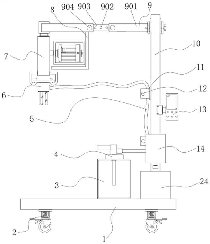
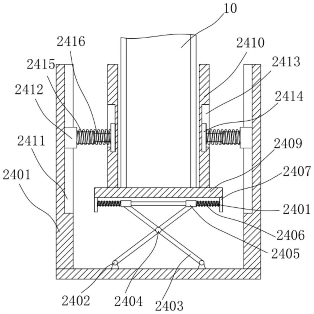
[0039] Example 1: See Figure 1-7 , a medical magnetic resonance automatic disinfection device with a shock-absorbing and protective function, comprising a base 1 and a moving wheel 2, the four corners of the bottom of the base 1 are fixedly connected with the moving wheels 2, and the top of one side of the base 1 is equipped with a protective structure 24. The protective structure 24 includes a fixed frame 2401 and a rotating seat 2402. The fixed frame 2401 is fixed on the top of the base 1. The rotating seat 2402 is installed in the middle of the bottom wall of the fixed frame 2401. The rotating seat 2402 is connected with a cross bar 2403 through a movable pin. , the middle part of the cross bar 2403 is provided with a rotating shaft 2404, the upper end of the cross bar 2403 is provided with a moving sleeve 2405, the moving sleeve 2405 is provided with a sliding bar 2406, and the two ends of the sliding bar 2406 are provided with a limiting plate 2407, a limiting plate 2407 ...
Embodiment 2
[0042] see Figure 1-7 The lifting structure 10 is fixedly connected to the fixed cylinder 2410, the lifting structure 10 is fixedly connected to the top of one side of the base 1, the storage structure 14 is fixedly connected to one end of the lifting structure 10, and the controller 13 is fixedly connected to one side of the lifting structure 10, The other side of the lifting structure 10 is fixedly connected with a fixed groove 11, one end of the fixed groove 11 is movably connected with a plug 12, one side of the top of the lifting structure 10 is fixedly connected with an adjustable structure 9, and the inside of the adjustable structure 9 is fixed. A connecting rod 15 is connected, and a support rod 16 is fixedly connected between the adjustable structures 9 on one side of the connecting rod 15. The bottom end of the connecting rod 15 is fixedly connected with a placement plate 8, and a box body 3, the top of the box body 3 is fixedly connected with an air pump 4, the in...
Embodiment 3
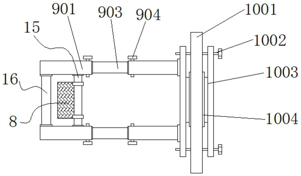
[0048] Embodiment 3: The adjustable structure 9 is composed of a sleeve 901, a reserved hole 902, a fixed rod 903 and an insert block 904. One side of the sleeve 901 is fixedly connected to one side of the slider 1003, and the inside of the sleeve 901 A fixed rod 903 is provided, and one end of the fixed rod 903 is provided with a reserved hole 902, and one end of the sleeve 901 is movably connected with an insert 904;
[0049] The inner diameter of the sleeve 901 is larger than the outer diameter of the fixed rod 903, the fixed rod 903 is embedded in the sleeve 901, and a telescopic structure is formed between the sleeve 901 and the fixed rod 903;
[0050] Specifically, as figure 1 and image 3 As shown, because the inner diameter of the sleeve 901 is larger than the outer diameter of the fixed rod 903, using the telescopic relationship between the fixed rod 903 and the sleeve 901, if the width needs to be adjusted, the plug 904 is opened, and the sleeve 901 is pulled Open ...
PUM
 Abstract
Description
Claims
Application Information
 - R&D
- Intellectual Property
- Life Sciences
- Materials
- Tech Scout
- Unparalleled Data Quality
- Higher Quality Content
- 60% Fewer Hallucinations
Browse by: Latest US Patents, China's latest patents, Technical Efficacy Thesaurus, Application Domain, Technology Topic, Popular Technical Reports.
© 2025 PatSnap. All rights reserved.Legal|Privacy policy|Modern Slavery Act Transparency Statement|Sitemap|About US| Contact US: help@patsnap.com


