Heat dissipation module

A technology of heat dissipation module and drive module, which is applied in cooling/ventilation/heating transformation, electrical equipment structural parts, electrical components, etc. , to achieve high heat dissipation efficiency and increase the effect of air intake

Active Publication Date: 2020-12-22
COMPAL ELECTRONICS INC
View PDF13 Cites 0 Cited by
  • Summary
  • Abstract
  • Description
  • Claims
  • Application Information

AI Technical Summary

Problems solved by technology

[0003] However, existing consumer electronic products such as computers and handheld devices are all developing towards thinner and easier to carry. Lighter and thinner also means that the space inside the electronic product is getting smaller and smaller, and it is impossible to place a heat dissipation module with better heat dissipation efficiency. When using When using a smaller cooling module, the required cooling efficiency cannot be achieved

Method used


Image

  • Heat dissipation module
  • Heat dissipation module
  • Heat dissipation module

Examples


Embodiment Construction

[0041] The aforementioned and other technical content, features and effects of the present invention will be clearly presented in the following detailed description of a preferred embodiment with reference to the accompanying drawings. The directional terms mentioned in the following embodiments, such as: up, down, left, right, front or back, etc., are only referring to the directions of the drawings. Accordingly, the directional terms are used to illustrate and not to limit the invention.

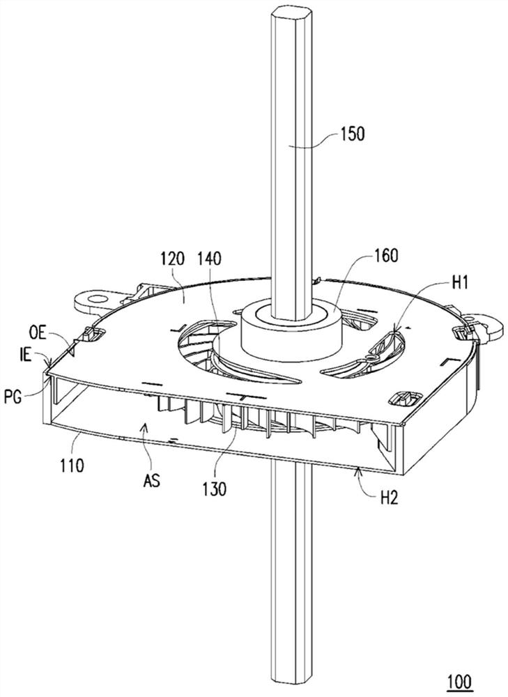
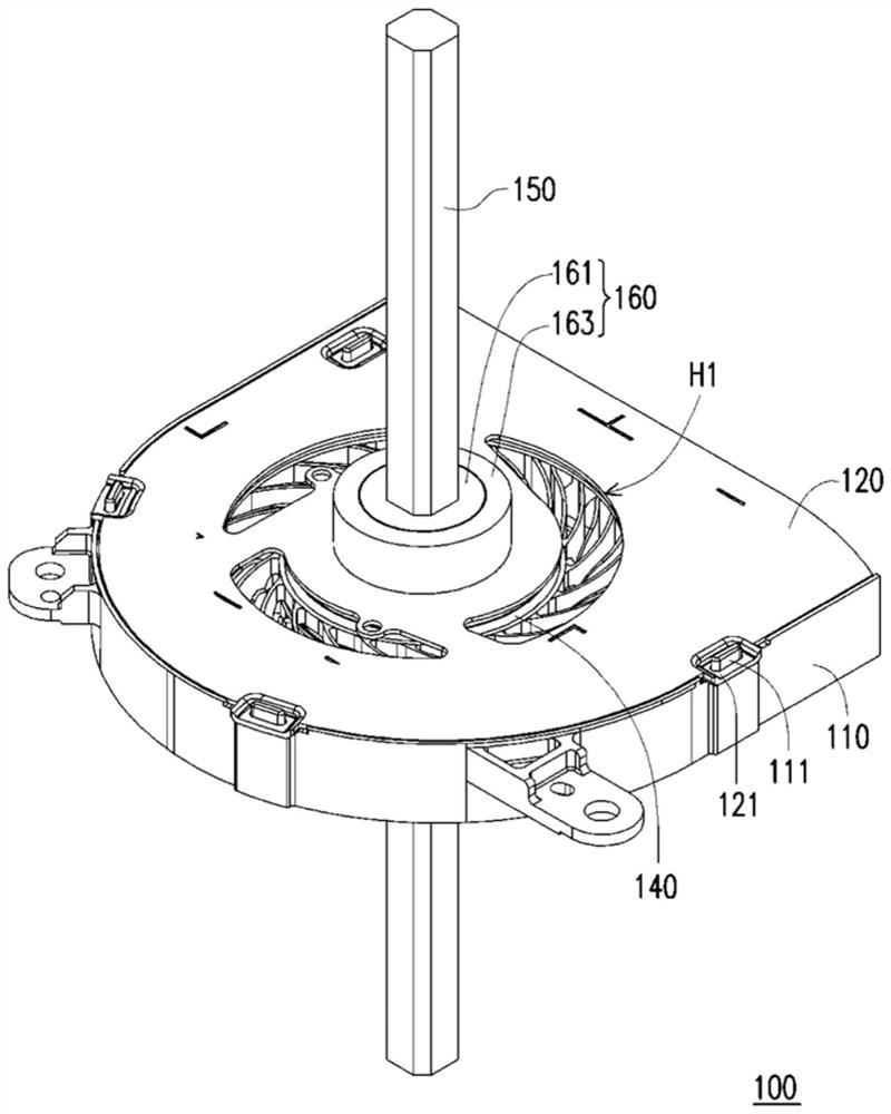
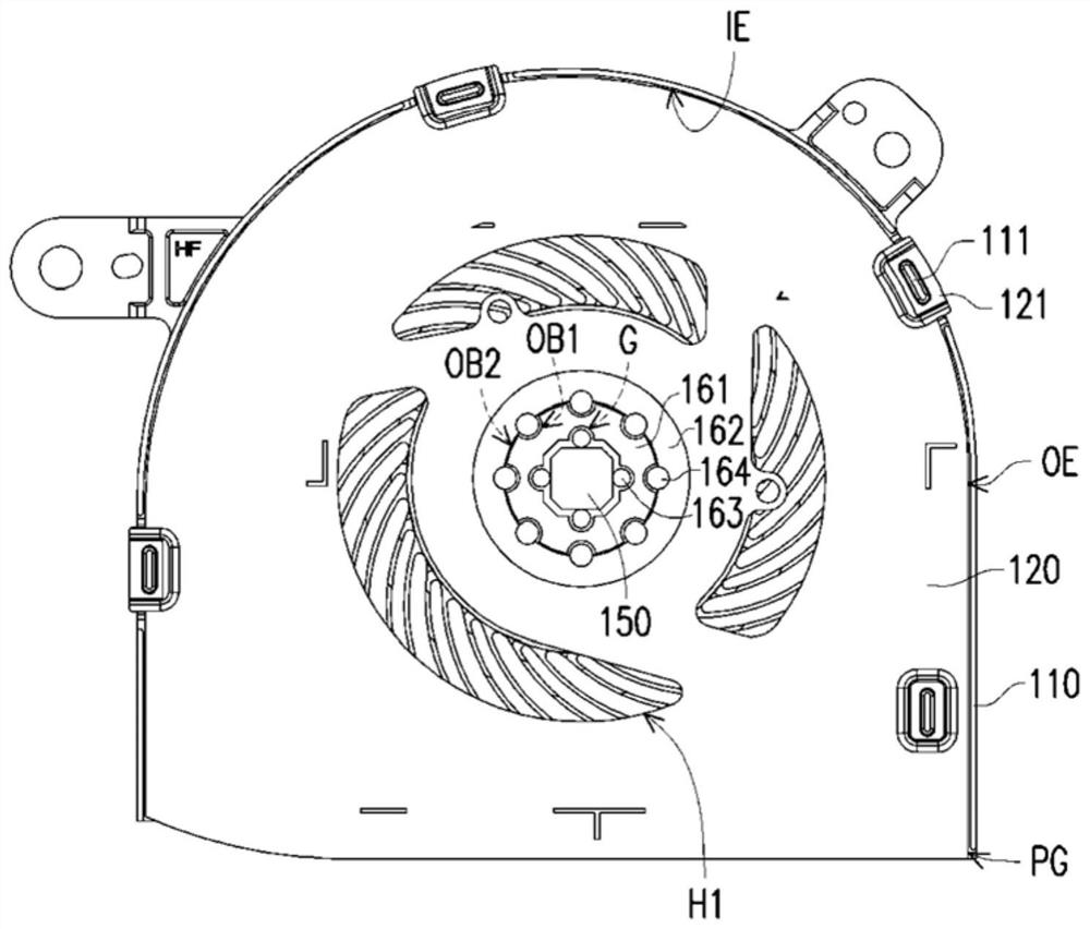
[0042] Figure 1A It is a three-dimensional schematic diagram of a heat dissipation module according to an embodiment of the present invention. Figure 1B yes Figure 1A A three-dimensional schematic diagram of the cooling module in the other direction. Figure 1C yes Figure 1A The top plan view of the cooling module. Figure 2A yes Figure 1A Component exploded schematic diagram of the heat dissipation module. Figure 2B yes Figure 1A The exploded schematic diagram of components in t...


PUM


Abstract

The invention provides a heat dissipation module. The heat dissipation module comprises a first shell, a second shell, a first fan assembly, a second fan assembly and a rotating shaft, the first shelland the second shell are slidably connected with each other and jointly form a containing space. The first fan assembly is arranged in the containing space and provided with a first hub and a plurality of first fan blades. The first hub is connected to the first shell. The second fan assembly is arranged in the containing space and provided with a second hub and a plurality of second fan blades,and the second hub is connected to the second shell. And the first hub and the second hub are overlapped with each other. The rotating shaft is pivoted to the first shell and the second shell and clamped to the first fan assembly and the second fan assembly.

Description

technical field [0001] The present invention relates to a heat dissipation module, and in particular to a heat dissipation module capable of changing air flow. Background technique [0002] Today's consumer electronic products benefit from the improvement of semiconductor manufacturing process, which makes the computing performance of the processing chip more excellent, and the temperature during operation is also gradually increased. When the temperature is too high, it will affect the operation stability of the chip, so good heat dissipation is the key to modern electronic products. The existing heat dissipation method mainly installs a heat dissipation module on the casing to discharge the hot air inside the body and introduce cold air. Through air convection, the processing chip is dissipated to maintain a stable operating temperature. [0003] However, existing consumer electronic products such as computers and handheld devices are all developing towards thinner and ea...

Claims


Application Information

Patent Timeline
Patent Type & Authority Applications(China)
IPC IPC(8): H05K7/20
CPCH05K7/20172H05K7/20145F04D25/02F04D29/053F04D27/002F04D29/4226F04D25/166F04D25/08
Inventor 黄瑞闵江志文陈千茱蓝伟豪杜青亚林肯平
Owner COMPAL ELECTRONICS INC
Why Eureka
Try Eureka