Light source group and backlight module

A technology of backlight module and light source group, which is applied in the direction of light source, electric light source, point light source, etc., can solve the problem that the configuration density of light emitting diode cannot be improved, and achieve the effect of good light output effect.

Inactive Publication Date: 2013-04-24
华映视讯(吴江)有限公司 +1
View PDF0 Cites 0 Cited by
  • Summary
  • Abstract
  • Description
  • Claims
  • Application Information

AI Technical Summary

Problems solved by technology

[0006] The present invention also provides a backlight module to solve the problem that the arrangement density of light emitting diodes in the known backlight module cannot be increased

Method used


Image

  • Light source group and backlight module
  • Light source group and backlight module
  • Light source group and backlight module

Examples


Embodiment Construction

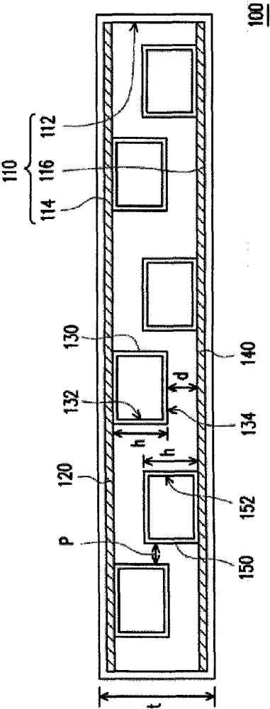
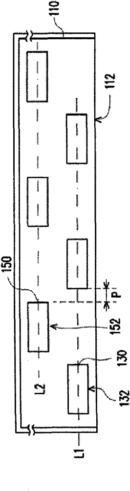
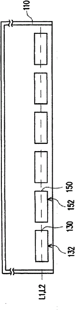
[0023] figure 1 It is a schematic diagram of a light source group according to an embodiment of the present invention. Please refer to figure 1 The light source group 100 includes a lampshade 110 , a first circuit board 120 , a plurality of first point light sources 130 , a second circuit board 140 and a plurality of second point light sources 150 . The lampshade 110 has an opening 112 , a first side 114 and a second side 116 , and the first side 114 and the second side 116 are respectively located on opposite sides of the opening 112 . The first circuit board 120 is disposed on the first side 114 . The first point light sources 130 are disposed on the first circuit board 120 , and each first point light source 130 has a first light emitting surface 132 facing the opening 112 and a first top surface 134 away from the first circuit board 120 . The second circuit board 140 is disposed on the second side 116 and is substantially parallel to the first circuit board 120 . The s...


PUM


Abstract

The invention relates to a light source group which comprises a lamp cover, a first circuit board, a plurality of first point light sources, a second circuit board and a plurality of second point light sources, wherein the lamp cover is provided with an opening, a first side and a second side, and the first side and the second side are respectively positioned at the two opposite sides of the opening; the first circuit board is arranged on the first side; the first point light sources are arranged on the first circuit board, and each first point light source is provided with a first light-emitting surface facing to the opening and a first top surface far away from the first circuit board; the second circuit board is arranged on the second side and is substantially parallel to the first circuit board; and the second point light sources are arranged on the second circuit board, and each second point light source is provided with a second light-emitting surface facing to the opening, wherein the distance between the first top surface and the second circuit board is less than the height of the second point light sources.

Description

technical field [0001] The present invention relates to a light source group and a backlight module, and in particular to a light source group and a backlight module with point light sources arranged on different circuit boards. Background technique [0002] With the substantial improvement of computer performance and the high development of Internet and multimedia technology, most of the transmission of image information has been converted from analog to digital transmission. In order to adapt to the modern life style, the volume of video or image devices is becoming thinner and thinner day by day. Although the traditional cathode ray display (CRT) still has its advantages, due to the structure of the internal electronic cavity, the display is bulky and takes up space, and there are still problems such as radiation when displaying. Therefore, the flat panel display (Flat Panel Display), such as liquid crystal display (LCD), organic laser display (OLED) or plasma display (P...

Claims


Application Information

Patent Timeline
Patent Type & Authority Patents(China)
IPC IPC(8): F21S8/00F21V3/02F21V23/00F21V19/00G02F1/13357F21Y101/02
Inventor 张家骏
Owner 华映视讯(吴江)有限公司
Why Eureka
Try Eureka