A one-cable dual-core lc-type optical fiber connector

An optical fiber connector and connector technology, which is applied to instruments, optics, light guides, etc., can solve the problems of damage to optical fiber active connectors, small operation space, troublesome replacement of polarity, etc., to achieve simple and reliable structure, improve use density, save money The effect of manipulating the space

Active Publication Date: 2019-02-15
NANJING PUTIAN TELEGE INTELLIGENT BUILDING
View PDF6 Cites 1 Cited by
  • Summary
  • Abstract
  • Description
  • Claims
  • Application Information

AI Technical Summary

Problems solved by technology

[0002] At present, traditional optical fiber connectors generally use fingers to directly pull the connecting sleeve or press the buckle to take out the optical fiber active connector, which limits the installation density of the optical fiber active connector
Among them, for the traditional optical fiber active connector used in high-density and ultra-high-density installations, the following problems will occur: 1. The operating space is extremely small, and the optical fiber active connector cannot be removed without the use of tools; 2. In the case of tools The operation of taking out the optical fiber active connector is complicated, and it is easy to damage the optical fiber active connector; 3. The traditional optical fiber active connector limits the use of multi-connector adapters, and cannot provide flexible usage methods; The polarity position in the core is reversed, and the polarity in the connector needs to be reversed. The ordinary connector cannot be disassembled, and it is troublesome to change the polarity
The above problems have always prevented the use of fiber optic active connectors in high-density and ultra-high-density applications more conveniently

Method used


Image

  • A one-cable dual-core lc-type optical fiber connector
  • A one-cable dual-core lc-type optical fiber connector
  • A one-cable dual-core lc-type optical fiber connector

Examples


Embodiment Construction

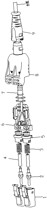
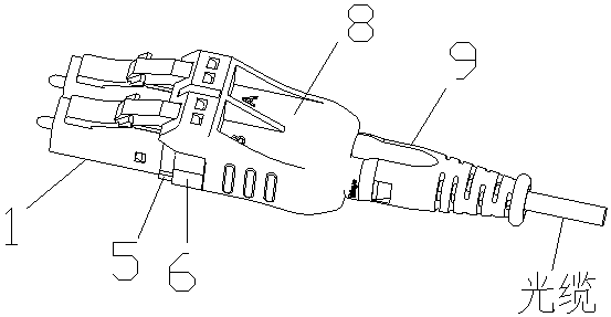
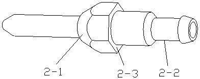
[0030] With reference to the drawings, a one-cable dual-core LC optical fiber connector is characterized by including a main bracket 1, a ferrule assembly 2, a spring 3, a heat shrink protection tube 4, an inner bracket 5, a base 6, a tail handle 7, and a shell 8. The tail sleeve 9; the ferrule assembly 2, the spring 3 and the heat-shrink protective tube 4 are inside the main bracket 1 and the inner bracket 5; the connector assembly light cable passes through the tail sleeve 9, the outer shell 8 and the tail handle 7. Peel off the base 6 into two cores, pass through the two inner brackets 5, and then pass through the heat-shrink protection tube 4, the spring 3, and end with the ferrule assembly 2. The heat-shrink tube 4 is heat-shrinked in the insert On the cylindrical surface 2-2 of the core assembly 2, the spring 3 is installed between the rear end surface 2-3 of the insert core assembly 2 and the inner end surface 5-3 of the inner bracket 5, and the front end surface 2-1 of t...


PUM


Abstract

The invention relates to a one-cable double-core LC optical fiber connector comprising main brackets, an insert core component, a spring, a heat-shrinkable protection tube, inner brackets, bases, a tail handle, a shell, and a tail sleeve. The tail sleeve is connected with the shell. The two bases are matched up and down, and the two inner brackets are embedded onto the bases respectively. The positioning clamp points of the main brackets are clamped into positioning holes of an adapter. An optical cable is divided into two cores in the base, and the cores are respectively connected with the two main brackets. The advantages are as follows: (1) a buckle on an elastic arm is in buckling fit with a buckle hole of the shell, the elastic arm can deform and go down when the tail sleeve is pulled, and thus, the LC connector is disconnected from the adapter; (2) the inner brackets can rotate on the bases respectively, the A and B polarities can be directly replaced by pulling the shell out and rotating the inner brackets, and thus, polarity replacement without disassembly is achieved; and (3) the LC optical fiber connector has a simple structure, is convenient to operate and can be easily plugged and pulled in a small space, the operation space is saved to the greatest extent, and the use density of the ports in communication equipment is improved.

Description

Technical field [0001] The invention relates to an optical fiber connector plug-in device for an optical cable, and belongs to the technical field of optical fiber connection devices. Background technique [0002] At present, traditional optical fiber connectors generally use fingers to directly pull the connection sleeve or press the buckle to take out the optical fiber movable connector, which limits the installation density of the optical fiber movable connector. Among them, for traditional optical fiber connectors used in high-density and ultra-high-density installations, the following problems will occur: 1. The operating space is very small, and the optical fiber connectors cannot be taken out without tools; 2. With the help of tools The operation of removing the fiber optic connector is complicated, and it is easy to damage the fiber optic connector; 3. The traditional fiber optic connector restricts the use of multiple adapters and cannot provide a flexible method of use;...

Claims


Application Information

Patent Timeline
Patent Type & Authority Patents(China)
IPC IPC(8): G02B6/38
CPCG02B6/3825G02B6/387
Inventor 李志宏关梦琳李超刘涛李广涛
Owner NANJING PUTIAN TELEGE INTELLIGENT BUILDING
Why Eureka
Try Eureka