
Household direct-suction wall-mounted range hood

A range hood and direct suction technology, which is applied in the directions of household stoves, household heating, household heating, etc., can solve the problems of inability to absorb smoke, inconvenience of equipment, occupation of cooking space, etc.

Inactive Publication Date: 2020-12-22
李端伟
View PDF0 Cites 2 Cited by
  • Summary
  • Abstract
  • Description
  • Claims
  • Application Information

AI Technical Summary

Problems solved by technology

[0003] But the existing direct-suction range hood also has the following deficiencies in the actual work process: first, after the existing range hood is installed and fixed, the distance between its range hood and the cooking range is also fixed thereupon. The cooking fume is sucked into the interior, and the distance is too small to occupy the cooking space, and the smoke inlet of the fume cover is placed directly above the stove, generally slightly higher than the top of people's heads, which is not convenient for cleaning the fume cover during actual use; secondly, household stoves Generally, there are two furnace mouths. The direct suction range hood can only be installed relative to the middle part during use, so it can only absorb the oil fume in a small range, and cannot complete the complete absorption of the fume, especially the two When two stoves work together, the fume in the whole room cannot be efficiently discharged to the outside space. At the same time, due to the large amount of fume diffused, not only the eyes and other organs of the personnel will be damaged by the fume, but also the desktop and other items will be stained with greasy oil. Make the personnel have to clean the corresponding items, make the personnel waste a lot of time, and make the equipment inconvenient

Method used


Image

  • Household direct-suction wall-mounted range hood
  • Household direct-suction wall-mounted range hood
  • Household direct-suction wall-mounted range hood

Examples


Embodiment Construction

[0019] The following will clearly and completely describe the technical solutions in the embodiments of the present invention with reference to the accompanying drawings in the embodiments of the present invention. Obviously, the described embodiments are only some, not all, embodiments of the present invention. Based on the embodiments of the present invention, all other embodiments obtained by persons of ordinary skill in the art without making creative efforts belong to the protection scope of the present invention.

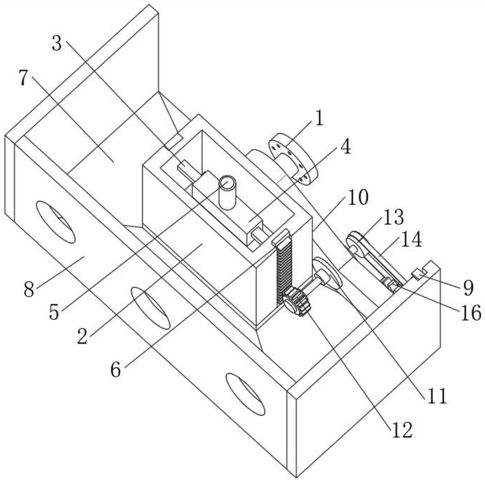
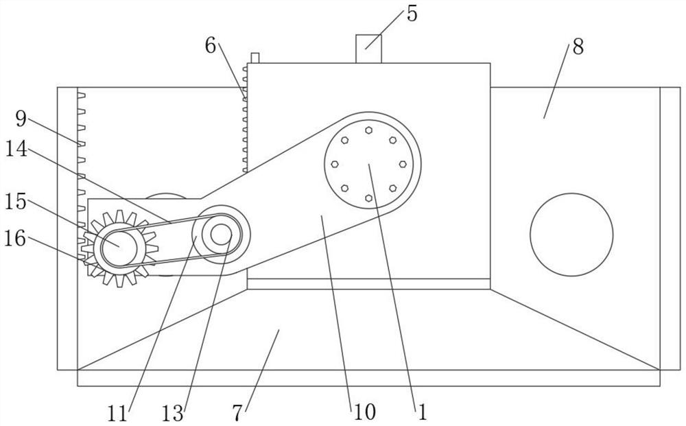
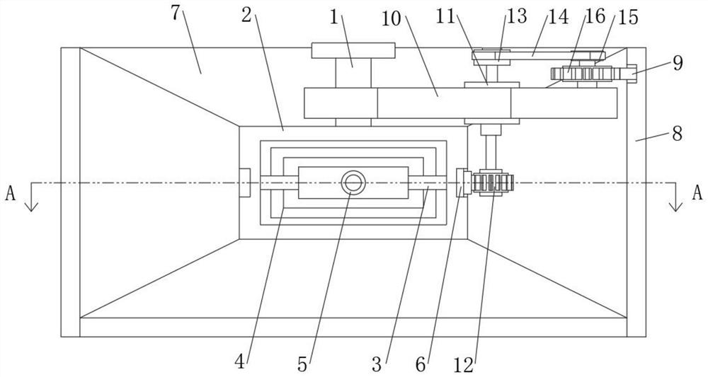
[0020] see Figure 1-5 , a household direct-suction wall-mounted range hood, comprising a support base 1, one end of the support base 1 is fixedly connected with a protective cover 2, the inside of the protective cover 2 is fixedly connected with a support frame 3, and the other end of the support frame 3 is fixedly connected with a The telescopic sleeve 4, the upper end of the telescopic sleeve 4 is fixedly connected with a smoke exhaust pipe 5, one side of t...


PUM


Abstract

The invention relates to the technical field of smart home, and discloses a household direct-suction wall-mounted range hood. The household direct-suction wall-mounted range hood comprises a supporting base, wherein a protective cover is fixedly connected to one end of the supporting base; and a supporting frame is fixedly connected into the protective cover. Through arrangement for a control structure, a double-shaft motor, a first gear and a movable rack, when a cooking bench generates a large amount of lampblack or the range hood needs to be cleaned, the double-shaft motor can be controlledto work, the first gear rotates to drive the movable rack meshed with the first gear to move downwards, and meanwhile, a telescopic sleeve extends and drives a lampblack hood to move downwards; a distance between a smoke suction port of the lampblack hood and a cooking range is adjusted to be close, so that the coverage area of the lampblack hood can be enlarged, lampblack can be rapidly adsorbedby the range hood, lampblack diffusion is reduced, the indoor environment is improved, and when the range hood needs to be cleaned, the lampblack hood is lowered similarly, so that the purpose of conveniently cleaning the range hood by people is achieved; and meanwhile, the range hood can be controlled to be located at the optimal lampblack suction position.

Description

technical field [0001] The invention relates to the technical field of smart home, in particular to a household direct-suction wall-mounted range hood. Background technique [0002] Range hood, also known as range hood, is a kitchen appliance that purifies the kitchen environment. It is installed on the top of the kitchen stove, which can quickly take away the waste burned by the stove and the oil fume harmful to the human body produced during the cooking process, and discharge it to the outside. At the same time, it condenses and collects the oil fume to reduce pollution and purify the air. Protection function, which is mainly divided into direct suction type and side suction type, of which the direct suction range hood is widely used. [0003] But the existing direct-suction range hood also has the following deficiencies in the actual work process: first, after the existing range hood is installed and fixed, the distance between its range hood and the cooking range is als...

Claims


Application Information

Patent Timeline
IPC IPC(8): F24C15/20
CPCF24C15/20F24C15/2085
Inventor 不公告发明人
Owner 李端伟
Learn More