Sealed fishing tool and fishing method

A salvage tool and basket-type technology, which is applied in the field of workover operations under pressure in oil and gas fields, and can solve the problem that the salvage tool cannot be under pressure.

Pending Publication Date: 2020-12-22
BC P INC CHINA NAT PETROLEUM CORP +1
View PDF0 Cites 0 Cited by
  • Summary
  • Abstract
  • Description
  • Claims
  • Application Information

AI Technical Summary

Problems solved by technology

[0003] The invention provides a sealed fishing tool and a fishing method, which solves the problem that the existing fishing tools cannot work under pressure in a gas well, and realizes the fishing of fallen objects in a gas well under pressure

Method used


Image

  • Sealed fishing tool and fishing method

Examples


Embodiment 1

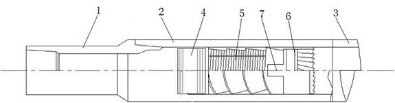
[0026]Referencefigure 1, Is a schematic structural diagram of Embodiment 1 of the present invention, a sealed fishing tool, including:

[0027]Upper joint 1;

[0028]Cylinder body 2, the inner circumferential surface of the upper end of the cylinder body 2 is threadedly connected with the lower end of the upper joint 1, and the cylinder body 2 is sequentially provided with a sealing rubber cylinder 4, a basket slip 5 and a milling control ring 6;

[0029]The guide shoe 3 is threadedly connected with the upper end of the guide shoe and the lower end of the cylinder 2. .

[0030]In actual use: the drill pipe is threaded with the upper joint 1 and drilled into the gas well. The upper joint 1, the barrel 2 and the guide shoe 3 are lowered above the falling object, and the drill pipe is slowly started to make the upper joint 1, the barrel The body 2 and the guide shoe 3 follow the rotation, and then drill down. The tip of the falling object is guided into the guide shoe 3 through the rotating shoe 3...

Embodiment 2

[0032]Referencefigure 1The difference of this embodiment is that: the inner circumferential surface of the cylinder body 2 is sequentially opened with a rubber cylinder seat, a slip cavity and a clamping groove, the sealing rubber cylinder 4 is embedded in the rubber cylinder seat, and the milling control The ring 6 is embedded in the slot, the basket slip 5 is arranged in the slip cavity, the upper end of the basket slip 5 is in contact with the lower end of the sealant cylinder 4, and the lower end of the basket slip 5 is in contact with the milling control The upper end of the ring 6 contacts.

[0033]In actual use: when the sealant cylinder 4 is squeezed, the sealant cylinder 4 is limited by the cylinder seat to move upward, causing the sealant cylinder 4 to expand inward and outward at the same time, and the sealant cylinder 4 is squeezed into the sealing seat. At the same time, the sealant cylinder 4 can restrict the falling objects from passing through the basket slip 5 and cont...

Embodiment 3

[0035]Referencefigure 1The difference of this embodiment is that the cylinder 2, the sealant cylinder 4, the basket slip 5 and the milling control ring 6 are coaxial.

[0036]In actual use: the cylinder body 2, the sealant cylinder 4, the basket slip 5 and the milling control ring 6 are coaxial, which can ensure that the falling objects can be correctly guided into the basket slip 5 and prevent the falling objects from being biased against the sealant cylinder 4.


PUM


Abstract

The invention relates to the field of under-pressure workover treatment of oil and gas fields, in particular to a sealed fishing tool and a fishing method. The sealed fishing tool comprises an upper joint, a barrel body and a guide shoe, wherein the inner circumferential surface of the upper end of the barrel body is in threaded connection with the lower end of the upper joint, and a sealing rubber barrel, a basket type slip and a milling control ring are sequentially arranged in the barrel body; and the upper end of the guide shoe is in threaded connection with the lower end of the barrel body. Due to the fact that the sealing rubber barrel is adopted, the problem that a gap affected by air pressure exists between a fallen object and the basket type slip when the fallen object enters thebasket type slip is effectively solved, then tight meshing of the fallen object is achieved, the fishing success rate is increased, meanwhile, it is guaranteed that air can pass through the sealing rubber barrel, and therefore under-pressure operation is achieved; and due to the fact that the milling control ring with the annular inclined face is adopted, when the top end of the fallen object is ground, the guiding effect is achieved, and it is guaranteed that the fallen object enters the basket type slip.

Description

Technical field[0001]The invention relates to the field of workover operations under pressure in an oil and gas field, in particular to a sealed fishing tool and a fishing method.Background technique[0002]When the oil and gas field is operating, the tool will fall off and break into the well pipe, and it needs to be fished out. The gas well works under pressure from the complex pipe string above the double seal, and the drill tool under the pipe string cannot be sealed, so it is necessary to carry out the work in the pressure work device Salvage under pressure to ensure the safe lifting of completion tools and liner.Summary of the invention[0003]The invention provides a sealed fishing tool and a fishing method, which solves the problem that the existing fishing tool cannot work under pressure in a gas well, and realizes the salvage of fallen objects in a gas well under pressure.[0004]The technical problem solved by the present invention can be realized by the following technical sol...

Claims


Application Information

Patent Timeline
IPC IPC(8): E21B31/18E21B31/12
CPCE21B31/18E21B31/12
Inventor 谢涛王祖文刘国良都清旺王增军雷璠刘小会王金刚席仲琛柳志勇陈万林陈文博赵庆磊徐睿
Owner BC P INC CHINA NAT PETROLEUM CORP
Why Eureka
Try Eureka