
Component conveying device and method

A technology for conveying devices and components, applied in the directions of transportation and packaging, conveyor objects, etc., can solve the problems of scrapped products, easy sliding of components, troublesome product inspection, etc., to improve safety and solve the effect of low efficiency of repetitive work

Active Publication Date: 2020-12-22
BEIJING INST OF RADIO METROLOGY & MEASUREMENT
View PDF4 Cites 1 Cited by
  • Summary
  • Abstract
  • Description
  • Claims
  • Application Information

AI Technical Summary

Problems solved by technology

[0003] The current stage is in the transition period between traditionalization and automation. The traditional testing method is to manually insert each component into the testing instrument one by one with tweezers. Not only is the efficiency low, but the components are easy to slip during the operation, resulting in product failure In addition, the static electricity of the human body is transmitted to the components through metal tweezers, which will also cause troubles in the later inspection of the product

Method used


Image

  • Component conveying device and method
  • Component conveying device and method
  • Component conveying device and method

Examples


Embodiment 1

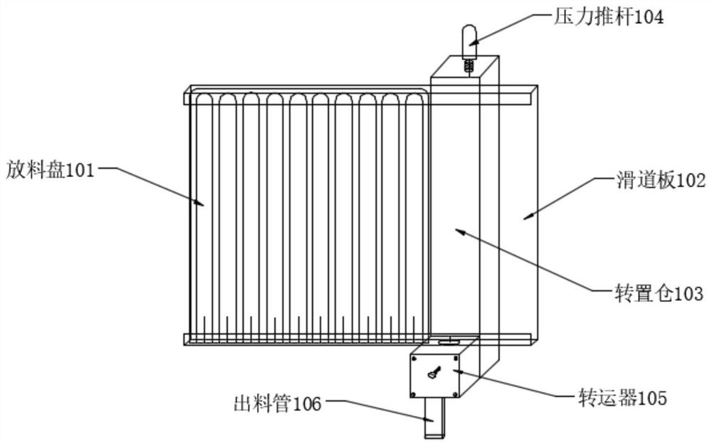
[0037] Such as figure 1 As shown, an embodiment of the present application provides a component delivery device, which includes: a discharge tray 101, a slideway plate 102, a pressure push rod 104, a transfer device 105 and a discharge pipe 106, wherein,

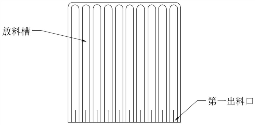
[0038] Such as figure 2 As shown, the discharge tray 101 is arranged on the slideway plate 102, and the discharge tray includes a plurality of mutually independent discharge troughs and a first outlet corresponding to the discharge troughs ( figure 2 shown in ), wherein, the discharge trough is used to store the components; the first outlet is used to transfer the components to the transfer device, it should be noted that the discharge tray 101 can be Disassembly, in the actual operation, you can prepare multiple discharge trays that store components with transmission. After the components of one discharge tray are transferred, you can directly replace them with another stored discharge tray, which is convenient. Rapid r...

Embodiment 2

[0052] Such as Figure 6 As shown, another embodiment of the present application provides a method for transferring components using the device described in Embodiment 1, the method comprising:

[0053] S10. Slide the discharging tray storing components to the notch position of the slideway plate;

[0054] S20. When the pressure push rod is in the first state, press down the pressure push rod to drive the transfer device to move from the initial position to transfer a component into the discharge pipe; when the pressure push rod is in the second state, Release the pressure push rod to drive the transfer device back to its original position and introduce the next component.

[0055] It should be noted that the first state is when the pressure push rod is pressed down, and the second state is when the pressure push rod is released. The above methods and steps can realize process production through automation of machinery and equipment, which should be understood by those skill...


PUM


Abstract

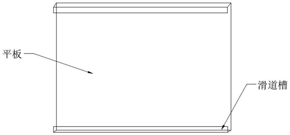
One embodiment of the invention discloses a component conveying device and method. The device comprises a slideway plate, a material containing plate, a transfer device and a pressure push rod. The slideway plate comprises a flat plate and slideway grooves, and a notch is formed in the predetermined position on the lower edge of each slideway groove. The material containing plate is arranged on the slideway plate, can be detached and comprises multiple material containing grooves independent of one another and first discharging ports corresponding to the material containing grooves. The material containing grooves are used for storing components. The slideway grooves are used for making the material containing plate slide to the predetermined position so that the first discharging ports can correspond to the notches. The transfer device is arranged below the slideway plate. The transfer device comprises a feeding port and a second discharging port. The feeding port corresponds to the notches, and the second discharging port corresponds to the feeding port. The pressure push rod is connected with the transfer device and is used for driving the transfer device to receive and convey the components.

Description

technical field [0001] This application relates to the field of component assembly. More specifically, it relates to a component delivery device and method. Background technique [0002] With the development of the times, military enterprises continue to grow and develop, and put forward higher standards for the quality standards and product cycle of components. It is necessary to ensure the improvement of product testing efficiency and the reduction of product damage rate, so as to provide testers with posed higher difficulty. [0003] The current stage is in the transition period between traditionalization and automation. The traditional testing method is to manually insert each component into the testing instrument one by one with tweezers. Not only is the efficiency low, but the components are easy to slip during the operation, resulting in product failure In addition, the static electricity of the human body is transmitted to the components through metal tweezers, whi...

Claims


Application Information

Patent Timeline
Patent Type & Authority Applications(China)
IPC IPC(8): B65G47/06B65G47/22B65G47/82
CPCB65G47/06B65G47/22B65G47/82
Inventor 仇昊郑文强范文杰甘家健高进平李慧军段友峰崔巍睢建平汪强
Owner BEIJING INST OF RADIO METROLOGY & MEASUREMENT
Learn More