Switch cabinet dolly contact overtravel measuring device

A measuring device and switchgear technology, applied in the direction of measuring devices, mechanical measuring devices, mechanical devices, etc., can solve the problems of inaccurate measurement, cumbersome measurement work, heat explosion, etc., and achieve convenient operation, stable and accurate measurement data, The effect of reducing waste

Active Publication Date: 2020-12-18
GUIZHOU POWER GRID CO LTD
View PDF5 Cites 0 Cited by
  • Summary
  • Abstract
  • Description
  • Claims
  • Application Information

AI Technical Summary

Problems solved by technology

However, in recent years, there have been incidents of switch cabinets being burned due to contact heating caused by poor contact.
One of the fundamental reasons is that the overtravel of the contacts of the switchgear trolley cannot meet the requirements of use, which increases the contact resistance and leads to heating failures
[0003] One of the reasons why the overtravel of the contact cannot meet the requirements of operation and use is that the switchgear is not constructed according to the installation and construction process requirements during the installation process and the debugging ability of the on-site technicians is limited. Because the switchgear adopts a fully enclosed structure, The overtravel inspection method is to apply conductive paste on the contact, and estimate whether the overtravel of the trolley contact is sufficient by the position of the indentation left on the conductive paste of the static contact when the switchgear trolley is working, and there is no other The method can measure the overtravel of the switch cabinet trolley contact
The measurement method of applying conductive paste also has the following problems. 1. The measurement is not accurate, because this method is that the trolley is pulled from the test position to the working position, and then pulled out from the working position to the test position, which will cause distortion of the indentation distance. , cannot reflect the real overtravel, and the light in the switch cabinet is dim, which is not conducive to observation
2. The measurement results vary from person to person. The measurement result obtained by this measurement method is an approximate value, which lacks scientific nature, and due to the difference in personal responsibility and ability, the measurement results vary greatly
3. The measurement efficiency is low and the measurement work is cumbersome. In order to see the indentation of the conductive paste as clearly as possible, it is necessary to apply more conductive paste evenly. Too thin or too thick is not conducive to the measurement of overtravel. Repeated many times, the conductive paste should be removed after the measurement, and it will lead to waste of materials
Since there is no scientific method or instrument for measuring the overtravel of the switchgear trolley contacts, many switchgears have left safety hazards since they were put into operation. As the current increases, heating and explosion incidents occur

Method used


Image

  • Switch cabinet dolly contact overtravel measuring device
  • Switch cabinet dolly contact overtravel measuring device
  • Switch cabinet dolly contact overtravel measuring device

Examples


Embodiment 1

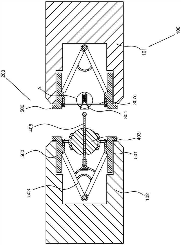
[0030] refer to Figure 1-Figure 3 , a switchgear trolley contact overtravel measuring device, including a measuring component 100, including a switchgear static contact 101, a switchgear trolley, and a moving contact 102 arranged at the front end of the switchgear trolley; and, cooperating with the detection component 200, It includes a measuring part 300 arranged on the static contact 101 and a connecting part 400 arranged on the front end of the moving contact 102 .

[0031] Specifically, the main structure of the present invention includes a measuring assembly 100. In this embodiment, the measuring assembly 100 includes a switchgear static contact 101. The static contact 101 of the switchgear is generally arranged inside the switchgear, and generally the static contact 101 There are several, set side by side in the switch cabinet, and then in order to be able to detect, there is also a switch cabinet trolley, the switch cabinet trolley is set separately from the switch cab...

Embodiment 2

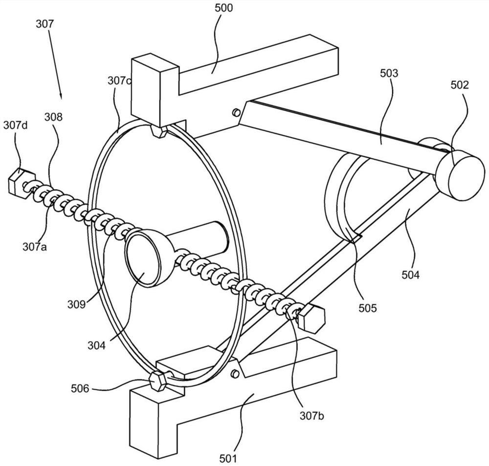
[0035] refer to Figure 1-Figure 5 , This embodiment is different from the first embodiment in that: the measuring part 300 includes a measuring piston 302 cavity 301 arranged on the static contact 101, a piston 302 slidingly connected in the measuring piston 302 cavity 301 and a piston 302 arranged on the piston The measuring ruler 303 on the 302, the front end of the measuring piston 302 cavity 301 is provided with a guide ring 304, the piston 302 and the measuring piston 302 cavity 301 are provided with a return spring 305, and the measuring piston 302 cavity 301 is provided with a The locking member 306, wherein, the outside of the measuring piston 302 cavity 301 is provided with an adjusting part 307, and the adjusting part 307 includes a first screw 307a and a second screw 307b connected to the side wall of the measuring piston 302 cavity 301, and the measuring piston 302 An elastic coil spring 307c is connected to the outside of the cavity 301, the first screw rod 307a ...

Embodiment 3

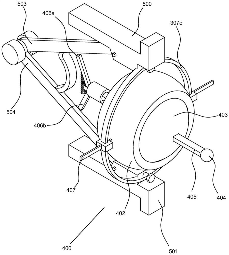
[0045] refer to Figure 2-Figure 6 , This embodiment is different from the above embodiments in that: the connecting part 400 includes a first positioning piece 500 and a second positioning piece 501 which are also arranged on the movable joint and an elastic coil spring 307c, and the elastic coil spring 307c is far away from the first positioning piece 500 and the second positioning member 501 are connected with a square guide bar 407, the movable joint is provided with a semi-hollow sphere 402 connected with the square guide bar 407, the semi-hollow sphere 402 is provided with a sphere 403, and the sphere 403 protrudes outwards. Measuring ball 404, a measuring rod 405 is threaded on the sphere 403, the measuring ball 404 is threadedly connected to the front end of the measuring rod 405, the rear end of the measuring rod 405 is connected with an adjustable limit piece 406, and the moving contact 102 is also hinged with a first splint 503 and the second splint 504, an adjustme...


PUM


Abstract

The invention discloses a switch cabinet dolly contact overtravel measuring device comprising: a measuring assembly which comprises a switch cabinet static contact, a switch cabinet dolly and a movingcontact arranged at the front end of the switch cabinet dolly; a matching detection assembly which comprises a measuring part arranged on the static contact and a connecting part arranged at the front end of the moving contact. The measured data can be more stable and accurate and the operation is convenient. According to the invention, the result can be obtained without multitime repeated measurement. Compared with the methods employing conductive paste, the measuring device can reduce the waste of materials, does not need to clean a measurement part after operation, and is very simple and convenient.

Description

technical field [0001] The invention relates to the technical field of switch cabinet measurement, in particular to a device for measuring the overtravel of a switch cabinet trolley contact. Background technique [0002] In the power system, the switchgear is widely used due to its advantages of good sealing and small footprint. However, in recent years, there have been incidents in the switchgear that caused the heating of the contacts caused by poor contact, which caused the switchgear to burn out from time to time. One of the fundamental reasons is that the overtravel of the contacts of the switchgear trolley cannot meet the requirements of use, which increases the contact resistance and leads to heating failures. [0003] One of the reasons why the overtravel of the contact cannot meet the requirements of operation and use is that the switchgear is not constructed according to the installation and construction process requirements during the installation process and the...

Claims


Application Information

Patent Timeline
Patent Type & Authority Applications(China)
IPC IPC(8): G01B21/02G01B5/02
CPCG01B21/02G01B5/02
Inventor 李宏才卢兴福郝越峰龙波樊三军周在邦杨艳牟春王竹韩胜国
Owner GUIZHOU POWER GRID CO LTD
Why Eureka
Try Eureka