Rotating shaft with vibration reduction device

A technology of vibration damping device and rotating shaft, which is applied in the direction of transmission device, transmission device parts, belt/chain/gear, etc., which can solve the problems of noise, reduce the service life of equipment, and generate vibration, so as to reduce vibration, facilitate use, The effect of reducing transmission efficiency

Pending Publication Date: 2020-12-15
常熟市天博金属制品有限公司
View PDF6 Cites 0 Cited by
  • Summary
  • Abstract
  • Description
  • Claims
  • Application Information

AI Technical Summary

Problems solved by technology

[0002] There are many transmission relationships between machines, and the mechanical power is transmitted to the terminal equipment through an intermediate medium. This transmission mode includes chain transmission, friction transmission, hydraulic transmission, gear transmission and belt transmission, etc. The most important power transmission is rotation. Relying on the rotating shaft for transmission, the long distance transmission adopts the combined transmission of pulley and transmission belt, but vibration will be generated during the transmission process, large vibration will affect the efficiency of power transmission, make noise, and reduce the service life of the equipment
[0003] The vibration reduction effect of the rotating shaft used in the traditional power transmission process is not obvious, and some of the rotating shafts are not equipped with a vibration-damping structure, which is not conducive to the smooth transmission of power. Larger vibrations will affect the efficiency of power transmission, generate noise, and reduce equipment lifespan

Method used


Image

  • Rotating shaft with vibration reduction device
  • Rotating shaft with vibration reduction device
  • Rotating shaft with vibration reduction device

Examples


Embodiment Construction

[0030] The following will clearly and completely describe the technical solutions in the embodiments of the present invention with reference to the accompanying drawings in the embodiments of the present invention. Obviously, the described embodiments are only some, not all, embodiments of the present invention. Based on the embodiments of the present invention, all other embodiments obtained by persons of ordinary skill in the art without making creative efforts belong to the protection scope of the present invention.

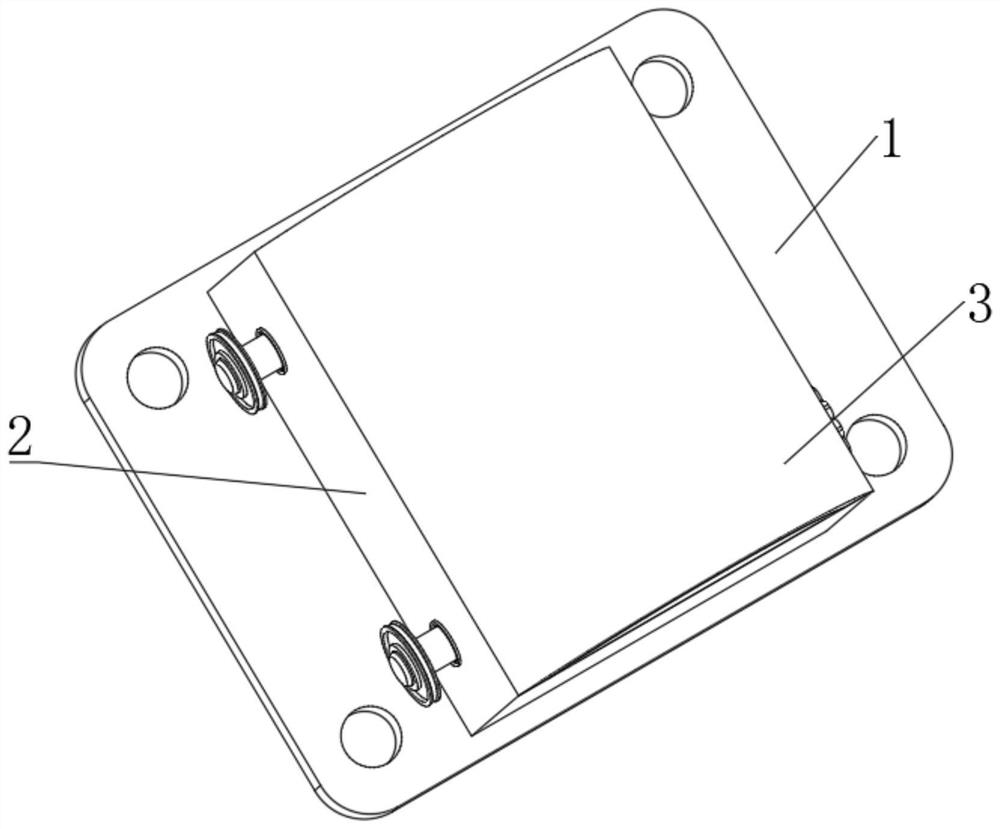
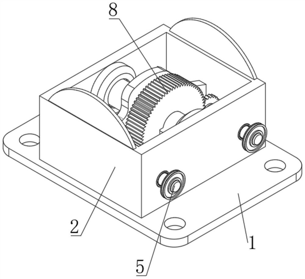
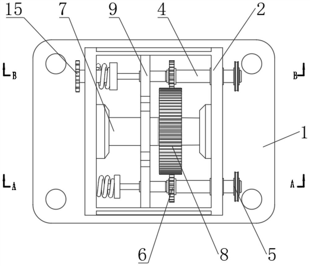
[0031] see Figure 1-5 , the present invention provides a technical solution: a rotating shaft with a damping device, including a fixed base 1, the top of the fixed base 1 is fixedly connected with a bottom cover 2, and the sides of the bottom cover 2 are movably connected with two sets of transmission shafts 4 through bearings, One end of the two sets of transmission shafts 4 is located outside the bottom cover 2 and fixedly connected with a pulley 5 for tran...


PUM


Abstract

The invention discloses a rotating shaft with a vibration reduction device. The rotating shaft comprises a fixed base, wherein the top of the fixed base is fixedly connected with a bottom cover, the side surface of the bottom cover is movably connected with two sets of transmission shafts through bearings, one ends of the two sets of transmission shafts are located outside the bottom cover and arefixedly connected with belt wheels, the other ends of the two sets of transmission shafts are located inside the bottom cover and are fixedly connected with pinions, a rotating shaft is movably connected to the interior of the bottom cover and located between the two transmission shafts, the side surface of the rotating shaft is fixedly connected with a gearwheel, and the gearwheel is in meshed transmission with the two pinions. The invention belongs to the technical field of rotating shafts. According to the rotating shaft, the two sets of transmission shafts are arranged, and are in transmission through the gearwheel and the pinions, vibration generated in the transmission process can be effectively reduced to be transmitted along with the rotating shaft, and the circumstances that violent vibration is caused and noises are generated during transmission of the second belt wheel, the transmission efficiency is reduced, and the service life is affected are avoided.

Description

technical field [0001] The invention relates to the technical field of a rotating shaft, in particular to a rotating shaft with a vibration damping device. Background technique [0002] There are many transmission relationships between machines, and the mechanical power is transmitted to the terminal equipment through an intermediate medium. This transmission mode includes chain transmission, friction transmission, hydraulic transmission, gear transmission and belt transmission, etc. The most important power transmission is rotation. Relying on the rotating shaft for transmission, the transmission of a long distance is combined with a pulley and a transmission belt, but vibration will be generated during the transmission process, and large vibration will affect the efficiency of power transmission, make noise, and reduce the service life of the equipment. [0003] The vibration reduction effect of the rotating shaft used in the traditional power transmission process is not o...

Claims


Application Information

Patent Timeline
Patent Type & Authority Applications(China)
IPC IPC(8): F16H37/12F16H57/023F16H57/028
CPCF16H37/12F16H57/023F16H57/028
Inventor 张伟强
Owner 常熟市天博金属制品有限公司
Why Eureka
Try Eureka