
Packaging detection equipment with classified clamping function for diode processing

A detection equipment and diode technology, which is applied in the field of packaging detection equipment with a classification and clamping function for diode processing, can solve problems such as affecting the health of workers and reducing the detection efficiency of diode packaging.

Inactive Publication Date: 2020-12-15
东莞市固德智能科技有限公司
View PDF0 Cites 1 Cited by
  • Summary
  • Abstract
  • Description
  • Claims
  • Application Information

AI Technical Summary

Problems solved by technology

[0004] The object of the present invention is to provide a kind of packaging and testing equipment with classification and clamping function for diode processing, so as to solve the traditional diode proposed in the above background technology. After the processing is completed, certain packaging and testing operations are required to ensure its effectiveness. , In the traditional diode packaging inspection work, most of the diode poles need to be manually detected with a multimeter. This detection method greatly reduces the efficiency of diode packaging inspection, and at the same time, some metal elements in the diode are easily inhaled by the staff. In the body, problems that affect the health of the staff

Method used


Image

  • Packaging detection equipment with classified clamping function for diode processing
  • Packaging detection equipment with classified clamping function for diode processing
  • Packaging detection equipment with classified clamping function for diode processing

Examples


Embodiment Construction

[0026] The technical solutions in the embodiments of the present invention will be clearly and completely described below in conjunction with the accompanying drawings in the embodiments of the present invention. Obviously, the described embodiments are only some of the embodiments of the present invention, not all of them. Based on The embodiments of the present invention and all other embodiments obtained by persons of ordinary skill in the art without making creative efforts belong to the protection scope of the present invention.

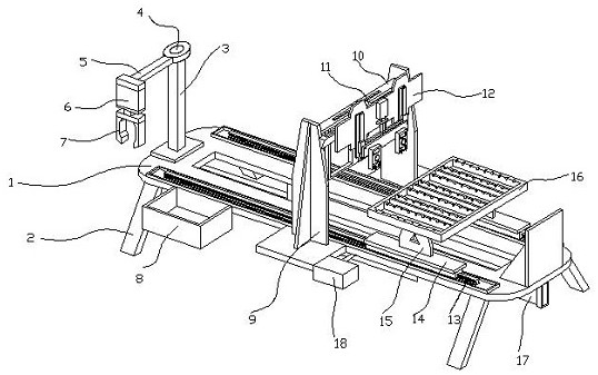
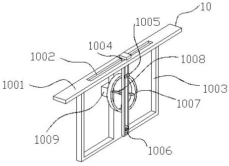
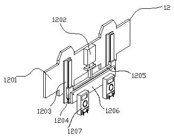
[0027] see Figure 1-5, the present invention provides a technical solution: a packaging and testing device for diode processing with a classification and clamping function, including a device body 1 and a second motor 18, the bottom of the device body 1 is provided with a leg 2, and the top of the device body 1 The left side is provided with a pole 3, the top of the pole 3 is provided with a turntable 4, and the front side of the turntable 4 is...


PUM


Abstract

The invention discloses packaging detection equipment with a classified clamping function for diode processing. The packaging detection equipment comprises a device body and a first containing cavity,side plates are arranged on the left side and the right side of the outer portion of the device body, rotating shafts are installed on the outer walls of the side plates, and a cover plate is arranged on the inner side of the first containing cavity; and the first containing cavity is located in the device body, second containing cavities are formed in the left side and the right side of the inner part of the device body, and lifting plates are arranged on the inner sides of the second containing cavities. According to an external heat dissipation device for a power bank, through the arrangement of the side plates, the device body forms a complete closed structure, by using the structural arrangement of the rotating shafts the cover plate can rotate on the side plates, the ventilation andheat dissipation environment in the device body is guaranteed through the arrangement of ventilation net plates on the side plates, the closed structure of the device body is adjusted through turnover control over the cover plate, and when the ventilation net plates are exposed, the device body has good heat dissipation capacity.

Description

technical field [0001] The invention relates to the technical field of diode packaging and testing, in particular to a packaging and testing device for diode processing with a classification and clamping function. Background technique [0002] A diode is an electronic device made of semiconductor materials (silicon, selenium, germanium, etc.), which has unidirectional conductivity, that is, when a forward voltage is applied to the anode and cathode of the diode, the diode conducts, and when the anode and cathode When the reverse voltage is added, the diode is cut off. The diode is one of the earliest semiconductor devices, and its application is very wide, especially in various electronic circuits, using diodes and resistors, capacitors, inductors and other components for reasonable connections. Circuits with different functions can realize various functions such as rectification of alternating current, detection of modulated signals, limiting and clamping, and voltage stabi...

Claims


Application Information

Patent Timeline
IPC IPC(8): B07C5/34B07C5/02B07C5/36
CPCB07C5/02B07C5/34B07C5/362
Inventor 谢思浩林俊乐
Owner 东莞市固德智能科技有限公司
Learn More