


Quick Research
Generate reliable direction feasibility study reports for your R&D in just a few steps.

Technical Q&A
Discover and master advanced knowledge NOW. Basics, ideas, possibilities, all at once.

Find Solutions
As an expert in R&D theories, this can generate solutions to your technical problems instantly.

Evaluate Feasibility
Analyze your overall solution with one click, know your potential R&D risks in advance.

Monitor Landscape
Get weekly tech updates, stay abreast of the latest tech innovations and key insights.
Chip inductor gluing machine
A gluing machine and inductance technology, which is applied in the manufacture of inductance/transformer/magnet, circuits, electrical components, etc. It can solve the problems of reducing the amount of glue on the inductor line, the height difference of the circuit board, and the effect of reducing the glue, so as to improve the effect, the effect of increasing the amount of glue
- Summary
- Abstract
- Description
- Claims
- Application Information
AI Technical Summary
Problems solved by technology
Method used
Image

Examples
Embodiment 1
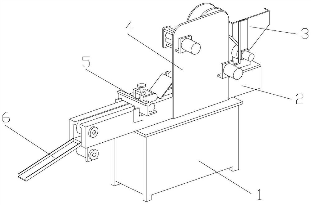
[0028] Example 1: Please refer to Figure 1-Figure 6 , the specific embodiments of the present invention are as follows:
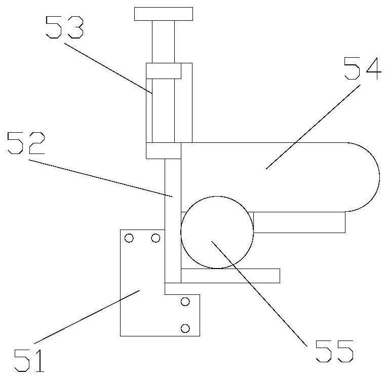
[0029] Its structure includes a chassis 1, a conveying line 2, a feeding hopper 3, a side plate 4, an adhesive structure 5, and a hopper 6. The conveying line 2 is installed horizontally on the upper end and is mechanically connected, and the feeding hopper 3 is vertically Installed on the upper end of the conveying line 2 and fixed by bolts, the side plate 4 is fixed on the side end of the conveying line 2 and welded with the chassis 1, the adhesive structure 5 is installed horizontally on the upper end of the conveying line 2 and straddles the conveying line 2 At the upper end, the discharge hopper 6 is installed at the lower left end of the conveying line 2 and is mechanically connected; the adhesive structure 5 includes a mounting plate 51, a bracket 52, an adjustment rod 53, a glue injection structure 54, and a pump body 55. The mounting plate 51 is ...
Embodiment 2
[0036] Example 2: Please refer to image 3 , Figure 7-Figure 8 , the specific embodiments of the present invention are as follows:
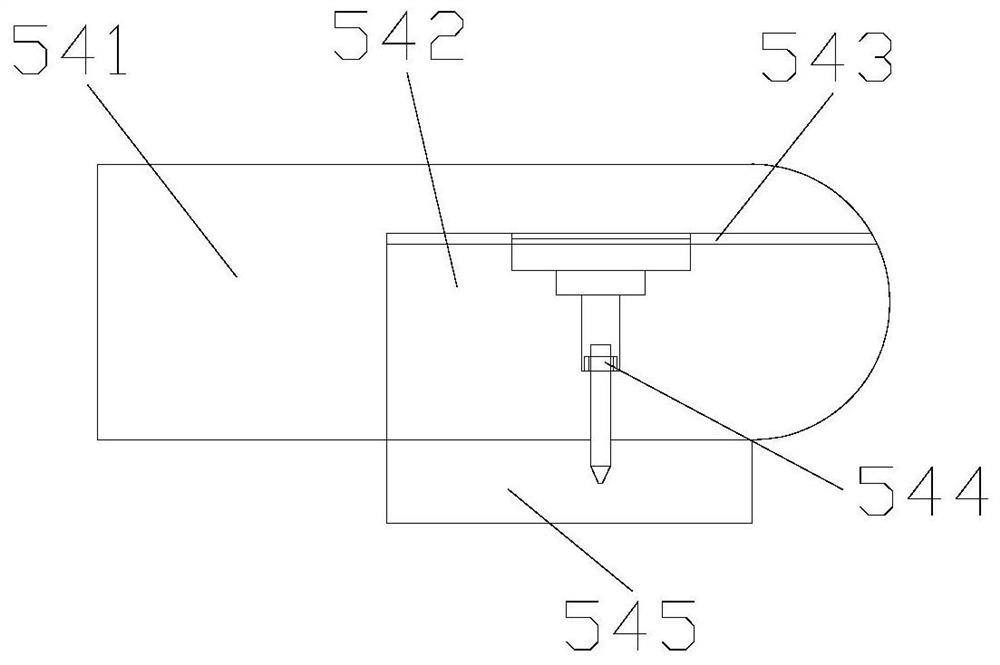
[0037] The glue injection structure 54 includes an outer frame 541, an inner groove 542, a slide rail 543, an adjustment structure 544, and a protective structure 545. The inner groove 542 is arranged inside the outer frame 541 and is an integrated structure, and the slide rail 543 is embedded The adjustment structure 544 is vertically installed on the lower end of the slide rail 543 and adopts a flexible connection. The protective structure 545 is horizontally installed on the lower end of the outer frame 541 and is arranged outside the adjustment structure 544 .
[0038] Referring to 7, the protective structure 545 includes a connecting frame 45a, an inner rail 45b, a limiting plate 45c, and a side movable plate 45d. Installed on the inner side of the inner rail 45b and adopts a flexible connection, the side movable plate 45d is hinged to th...
PUM
 Abstract
Description
Claims
Application Information
 - R&D Engineer
- R&D Manager
- IP Professional
- Industry Leading Data Capabilities
- Powerful AI technology
- Patent DNA Extraction
Browse by: Latest US Patents, China's latest patents, Technical Efficacy Thesaurus, Application Domain, Technology Topic, Popular Technical Reports.
© 2024 PatSnap. All rights reserved.Legal|Privacy policy|Modern Slavery Act Transparency Statement|Sitemap|About US| Contact US: help@patsnap.com