
Digital filtering device and method for oscilloscope bandwidth limitation

A bandwidth limiting and digital filtering technology, applied in the field of signal processing, can solve the problems of fixed bandwidth limiting value, signal distortion, high hardware cost, etc., and achieve the effect of wide limited bandwidth range, good flat characteristics, and easy modification

Inactive Publication Date: 2020-12-11
CHINA ELECTRONIS TECH INSTR CO LTD
View PDF6 Cites 0 Cited by
  • Summary
  • Abstract
  • Description
  • Claims
  • Application Information

AI Technical Summary

Problems solved by technology

Since the bandwidth limit of the amplifier chip is implemented by analog devices, the disadvantages of this method are: 1. The bandwidth limit has only a few gears; 2. The bandwidth limit value is relatively fixed and cannot be set flexibly; 3. The amplitude-frequency response in the passband Gaussian characteristics, easy to cause signal distortion; 4. Use special devices to achieve bandwidth limitation, which increases the complexity of debugging and maintenance, and the hardware cost is high
These performance and cost disadvantages limit the development and widespread application of oscilloscopes

Method used


Image

  • Digital filtering device and method for oscilloscope bandwidth limitation
  • Digital filtering device and method for oscilloscope bandwidth limitation
  • Digital filtering device and method for oscilloscope bandwidth limitation

Examples


Embodiment 1

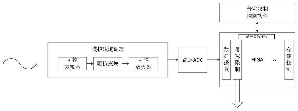
[0032] Embodiment 1 This embodiment provides a digital filter device for oscilloscope bandwidth limitation, the principle and structure are as follows figure 1 shown. The data it processes comes from the digital signal after ADC quantization, and the system consists of a control unit, a data receiving unit, a filtering parameter receiving unit and a bandwidth limiting filtering unit.

[0033] The bandwidth limiting filtering unit, the data receiving unit, and the filtering parameter receiving unit are all implemented in a programmable circuit such as a common FPGA without using any additional hardware circuits.

[0034] The functions of each unit and module are introduced as follows:

[0035] 1. The control unit is a control system developed based on the bandwidth limiting function of the oscilloscope. The control unit receives the bandwidth limiting commands and parameters set by the user through the input interface, transmits them to the bandwidth limiting filter unit insid...

Embodiment 2

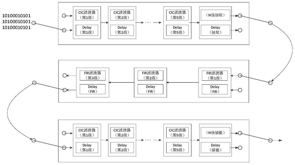
[0049] Embodiment 2 Based on the above-mentioned digital filtering device hardware equipment for oscilloscope bandwidth limitation, the digital filtering method for bandwidth limitation provided in this embodiment includes the following steps:

[0050] (1) The user inputs the bandwidth limit value through the oscilloscope human-computer interaction interface;

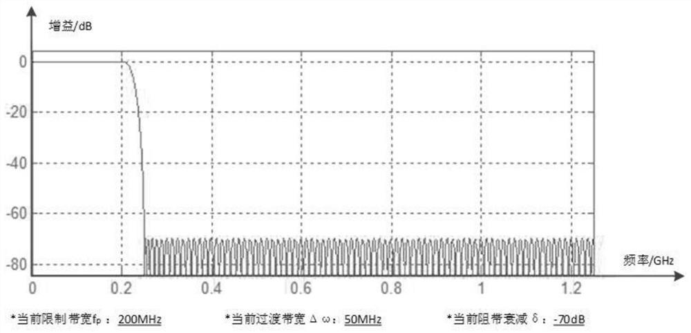
[0051] (2) The control unit analyzes the bandwidth limit value, calculates the required CIC series, sampling multiple, FIR filter parameters, interpolation multiple, post CIC series, etc. according to the established bandwidth limit gear, and at the same time gives the filtering effect model, giving the expected filtering results, such as image 3 Shown, so that the user has an intuitive impression on the senses and avoids misoperation of the settings;

[0052] (3) The data receiving unit receives the data quantized by the ADC, organizes it into a data format convenient for subsequent processing by the bandwidth limiti...

Embodiment 3

[0055] Embodiment 3 This embodiment provides a comparison test between the digital filter device and method of the present invention and the traditional analog chip bandwidth limitation.

[0056] The test scenario is to set the Fluke9500B to output a 600mVpp sine wave signal, the frequency is from 1MHz to 500MHz, and the step is 1MHz. The oscilloscope using the analog chip bandwidth limitation and the oscilloscope using the digital filtering device of the present invention are respectively tested, and the curve of amplitude changing with frequency is drawn, that is, the amplitude-frequency response curve of the oscilloscope.

[0057] Test results such as Figure 4 and 5 As shown, using the device and method of the present invention, its amplitude-frequency response curve is more flat in the 20MHz passband, and the time to drop to -70dB is very short, and the transition bandwidth is only about 8MHz through actual testing, which is obviously better than the traditional Analog ...


PUM


Abstract

The invention relates to a digital filtering device and method for oscilloscope bandwidth limitation. A digital filtering device for oscilloscope bandwidth limitation comprises a control unit configured to receive a bandwidth limitation command and parameters set by a user and control operation of a bandwidth limitation unit, a data receiving unit configured to receive the data quantized by the ADC and organize the data into a required data format, a filtering parameter receiving unit configured to receive the filtering parameter and the control command sent by the control unit, and a bandwidth limitation filtering unit comprising multiple stages of filtering modules with different bandwidth limits, and configured to perform parameter configuration on each filtering module under the control of the control unit so as to realize digital filtering under the bandwidth limit. According to the device and the method, a digital filtering technology is adopted, and the device and the method have the characteristics of large bandwidth limitation range, multiple gears and flexible setting when the bandwidth of the oscilloscope is limited; by adopting the multi-stage FIR, the filtering pass band has a good flatness characteristic.

Description

technical field [0001] The invention belongs to the technical field of signal processing, and in particular relates to a digital filtering device and method for limiting the bandwidth of an oscilloscope. Background technique [0002] In recent years, with the rapid development of DC power supply, automotive electronics, spectrum analysis and detection and other fields, the bandwidth limiting function of the oscilloscope has put forward a wide range, multi-level and other flexibility requirements. [0003] At present, the domestic common oscilloscope generally selects an amplifier chip with a bandwidth limiting function and places it on the signal link of the analog channel, and realizes bandwidth limitation by controlling the amplifier. Since the bandwidth limit of the amplifier chip is implemented by analog devices, the disadvantages of this method are: 1. The bandwidth limit has only a few gears; 2. The bandwidth limit value is relatively fixed and cannot be set flexibly; ...

Claims


Application Information

Patent Timeline
Patent Type & Authority Applications(China)
IPC IPC(8): G01R13/02H03H17/00H03H17/02
CPCG01R13/0209G01R13/0272H03H17/00H03H17/0202H03H17/0294H03H2017/0081
Inventor 刘永刘洪庆王啸郭同华邵建波向前王生伟
Owner CHINA ELECTRONIS TECH INSTR CO LTD
Learn More