
Reversible power device based on cooperation of servo electric cylinder and hydraulic cylinder

A servo electric cylinder and power device technology, applied in the field of mechanical transmission, can solve the problems that the number of adaptive stages cannot be set too much, cannot meet the actual required efficiency, mechanical energy waste, etc., achieve low cost, high efficiency, stable output, and improve the use of Scope, the effect of reducing the difficulty of construction

Active Publication Date: 2020-12-11
NORTH CHINA ELECTRIC POWER UNIV (BAODING)
View PDF4 Cites 0 Cited by
  • Summary
  • Abstract
  • Description
  • Claims
  • Application Information

AI Technical Summary

Problems solved by technology

The hydraulic potential energy conversion device in the prior art realizes the balance of the load force through the cooperation of the hydraulic cylinder and the valve. Due to the addition of the valve, the energy loss in the conversion process of the hydraulic potential energy and the mechanical energy is huge, and the actual required efficiency cannot be achieved. Further consideration is to use the variable area automatic The principle of adaptation reduces the use of valves and improves energy conversion efficiency, but the variable area adaptive scheme can only generate discrete forces, and the number of adaptive series cannot be set too much, so it cannot be applied to working conditions where the demand force is a small value force
In addition, the linear electric device in the prior art achieves the balance of the load force through the cooperation of the servo motor and the screw. The linear electric device itself has high output efficiency, but if it generates a linear force that meets the demand and achieves the same efficiency output, the cost is very expensive. The actual engineering situation may not adopt
[0004] At the same time, it is a pity that neither the hydraulic device nor the linear electric device in the prior art can recover mechanical energy and convert it into electrical energy during its reverse operation, resulting in a large amount of waste of mechanical energy.

Method used


Image

  • Reversible power device based on cooperation of servo electric cylinder and hydraulic cylinder
  • Reversible power device based on cooperation of servo electric cylinder and hydraulic cylinder

Examples


Embodiment Construction

[0028] In order to make the objectives, technical solutions and advantages of the present invention clearer, the technical solutions in the embodiments of the present invention will be described in more detail below in conjunction with the drawings in the embodiments of the present invention. In the drawings, the same or similar reference numerals denote the same or similar elements or elements having the same or similar functions throughout. The described embodiments are some, but not all, embodiments of the invention. The embodiments described below by referring to the figures are exemplary and are intended to explain the present invention and should not be construed as limiting the present invention. Based on the embodiments of the present invention, all other embodiments obtained by persons of ordinary skill in the art without creative efforts fall within the protection scope of the present invention. Embodiments of the present invention will be described in detail below ...


PUM


Abstract

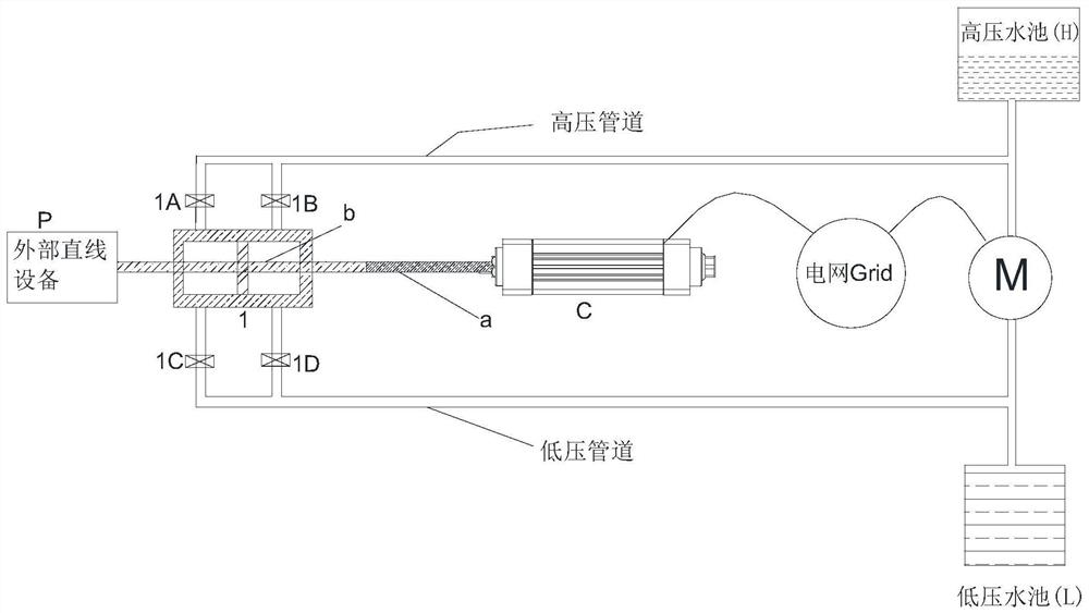
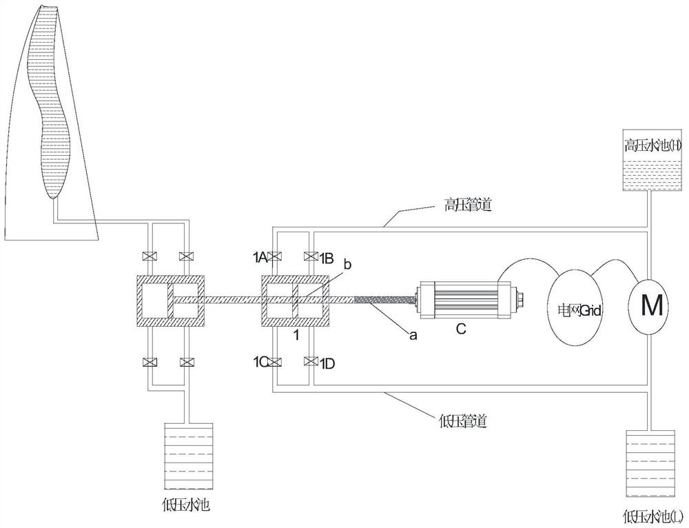
The invention discloses a reversible power device based on cooperation of a servo electric cylinder and a hydraulic cylinder. One end of electric equipment M is connected with a pressure-intensity-controllable high-pressure water pool H, and the other end of the electric equipment M is connected with a low-pressure water pool L; one end of a piston hydraulic cylinder 1 is connected with the pressure-controllable high-pressure water tank H, and the other end of the piston hydraulic cylinder 1 is connected with the low-pressure water tank L; a piston of the piston hydraulic cylinder 1 is slidably arranged in a cylinder body, a piston rod b is arranged on the piston, one end of the piston rod b is connected with a lead screw a of a turn-back type servo electric cylinder C, and the other end of the piston rod b is connected with external linear equipment P; a lead screw a of the turn-back type servo electric cylinder C is coaxially connected with the piston rod b of the hydraulic cylinder1 and the external linear equipment P; the turn-back type servo electric cylinder C and the electric equipment M are connected with a power grid; and the electric equipment M has two working states ofwater pumping and power generation, and the power device is controlled to convert electric energy into mechanical force or convert the mechanical force into electric energy.

Description

technical field [0001] The invention relates to the technical field of mechanical transmission, in particular to a reversible power device based on the cooperation of a servo electric cylinder and a hydraulic cylinder. Background technique [0002] With the construction of an innovative society and the continuous development of economy and technology, power devices that combine hydraulic potential energy and mechanical potential energy have become popular in social production links. With the increase in global energy demand and the deepening awareness of energy conservation and environmental protection, people are paying more and more attention to the stability and economy of energy storage technology in power equipment. [0003] For working conditions that require a linear force to balance the load force, the prior art often uses a hydraulic potential energy conversion device or a linear electric device to achieve. The hydraulic potential energy conversion device in the pr...

Claims


Application Information

Patent Timeline
Patent Type & Authority Applications(China)
IPC IPC(8): F03C1/26F03C1/007F03B13/00F04B17/03
CPCF03C1/26F03C1/007F04B17/03F03B13/00
Inventor 姜彤殷晨阳崔岩
Owner NORTH CHINA ELECTRIC POWER UNIV (BAODING)
Learn More