
Positioning and clamping equipment for PCB

A technology for clamping equipment and PCB boards, which is applied in the direction of circuit board tool positioning, workpiece clamping devices, electrical components, etc., and can solve problems such as unfavorable processing, damage to marble strength, and low marble strength

Inactive Publication Date: 2020-12-11
熊勇
View PDF5 Cites 6 Cited by
  • Summary
  • Abstract
  • Description
  • Claims
  • Application Information

AI Technical Summary

Problems solved by technology

[0002] In the process of PCB board processing, the PCB board often shakes and is very unstable. This phenomenon is not conducive to processing. Therefore, it is proposed to lay aluminum plates on the marble countertop to make room for the air clamp device. However, the plane of the aluminum plate The accumulated error of the degree error plus the flatness error of the marble surface is greater than the original error of the marble surface, so it is proposed to open a groove on the surface of the marble table, set the air clamp device in the marble, and only the clamping part exposes the surface of the marble table. Therefore, the surface of the marble countertop can be used as the reference surface, but opening grooves in the marble destroys the strength of the marble. The hardness of the marble itself is low, and the opening of the grooves leads to a smaller strength of the marble, resulting in a reduction in the service life of the marble platform

Method used


Image

  • Positioning and clamping equipment for PCB
  • Positioning and clamping equipment for PCB
  • Positioning and clamping equipment for PCB

Examples


Embodiment Construction

[0021] The specific implementation manners of the present invention will be further described in detail below in conjunction with the accompanying drawings and embodiments. The following examples are used to illustrate the present invention, but are not intended to limit the scope of the present invention.

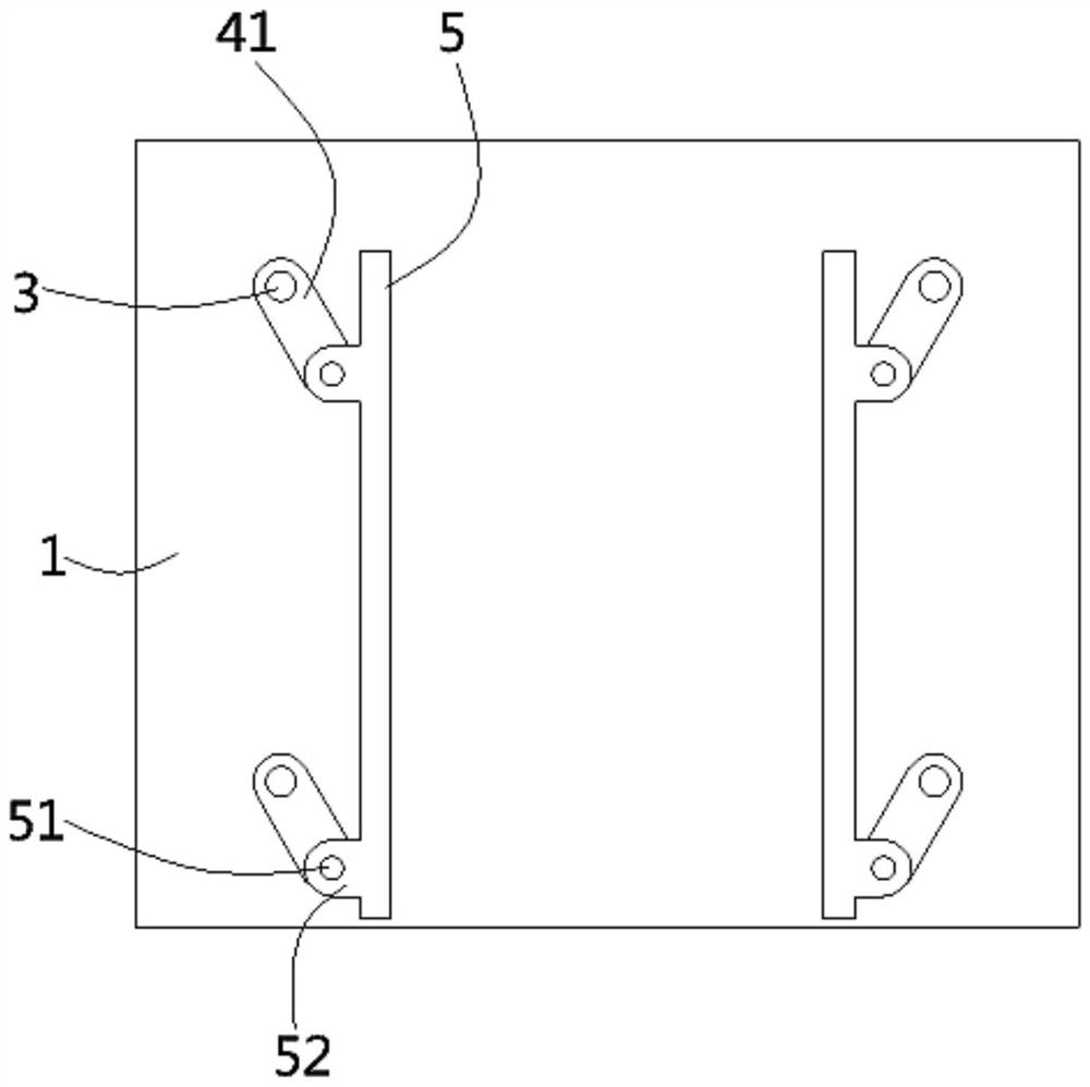
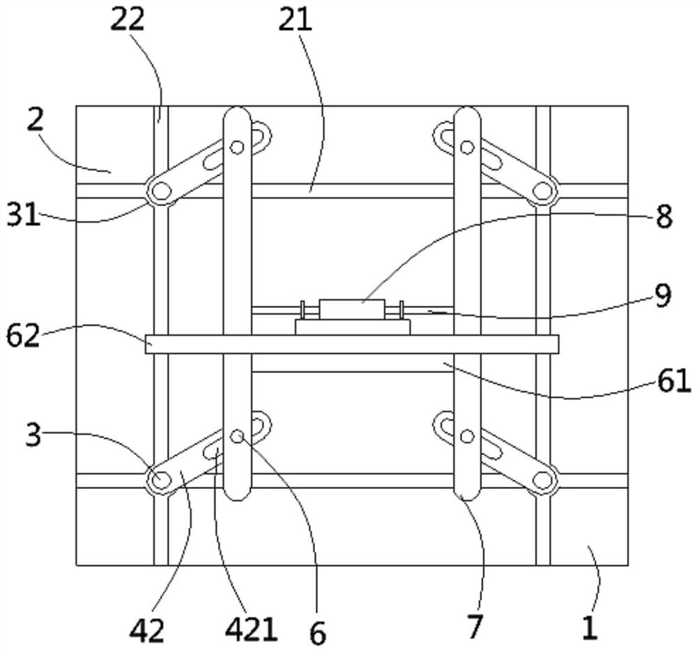
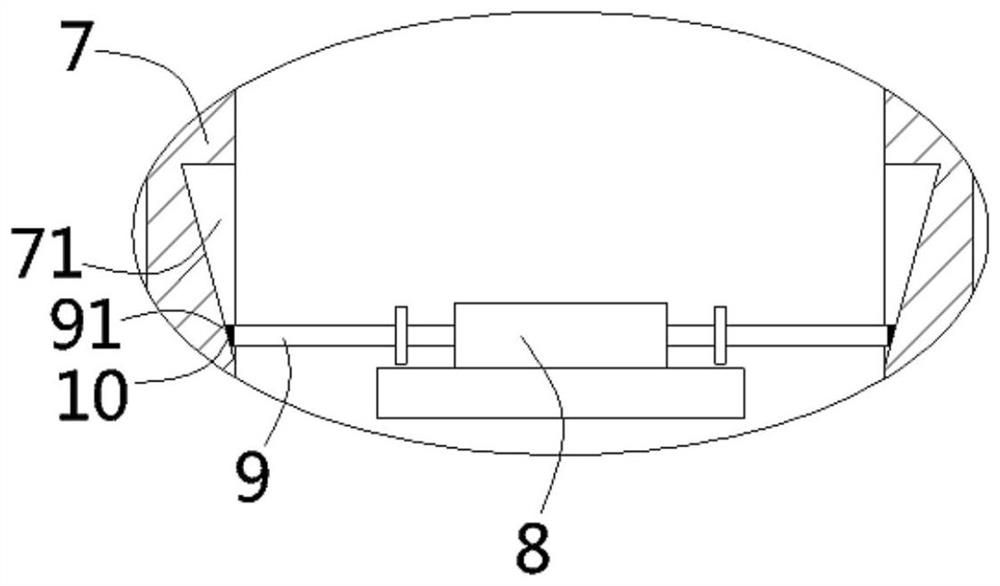
[0022] The following content reference Figure 1 to Figure 3 .

[0023] A positioning and clamping device for a PCB board according to the present invention comprises a marble platform 1, the lower end surface of the marble platform is embedded with a "well"-shaped rib 2, and the lower end surface of the rib is connected to the marble The lower end surface of the platform is on the same plane, and the ribs are composed of a transverse steel bar 21 and a longitudinal steel bar 22, the intersection of the transverse steel bar and the longitudinal steel bar is inserted with a coupling shaft 3, and the horizontal steel bar and the longitudinal steel bar The intersection is f...


PUM


Abstract

The invention discloses positioning and clamping equipment for a PCB. The positioning and clamping equipment comprises a marble platform, ribs are embedded and fixed to the lower end face of the marble platform, each rib is composed of a transverse steel bar and a longitudinal steel bar, a connecting shaft is inserted into the joint of each transverse steel bar and the corresponding longitudinal steel bar, and an inclined first connecting rod is fixed to the upper end of each connecting shaft in an inserted and sleeved manner. A longitudinal clamping strip is hinged to one end of each first connecting rod. Inclined second connecting rods are fixed to the lower ends of the connecting shafts in an inserted and sleeved manner, guide grooves are formed in the second connecting rods, pin shaftsare inserted into the guide grooves, longitudinal driving rods are fixed to the pin shafts, connecting plates are fixed to the longitudinal steel bars, the driving rods are inserted into the connecting plates, and a transverse double-shaft air cylinder is fixed to the middles of the connecting plates. Push rods are fixed to a piston rod of the double-shaft air cylinder, inclined grooves are formed in the opposite side walls of the driving rods, and one ends of the push rods are inserted into the inclined grooves and abut against the inner walls of the inclined grooves. According to the positioning and clamping equipment, while the strength of the marble platform can be guaranteed, the PCB can be conveniently and effectively clamped.

Description

technical field [0001] The invention relates to the technical field of PCB board processing devices, in particular to a positioning and clamping device for PCB boards. Background technique [0002] In the process of PCB board processing, the PCB board often shakes and is very unstable. This phenomenon is not conducive to processing. Therefore, it is proposed to lay aluminum plates on the marble countertop to make room for the air clamp device. However, the plane of the aluminum plate The accumulated error of the degree error plus the flatness error of the marble surface is greater than the original error of the marble surface, so it is proposed to open a groove on the surface of the marble table, set the air clamp device in the marble, and only the clamping part exposes the surface of the marble table. Thereby, the surface of the marble countertop can be used as the reference plane, but opening grooves in the marble destroys the strength of the marble. The hardness of the ma...

Claims


Application Information

Patent Timeline
IPC IPC(8): B25B11/00H05K3/00
CPCB25B11/00H05K3/0008
Inventor 熊勇
Owner 熊勇
Learn More