PCB welding table based on independent cooling technology

A PCB board, independent cooling technology, applied in welding equipment, auxiliary welding equipment, welding/cutting auxiliary equipment, etc., can solve the problems of difficult to meet the needs of the PCB board, unable to cool the PCB board, prolonged non-processing time, etc., to shorten the time The effect of non-processing time, avoiding welding slag scattering, and improving processing efficiency

Inactive Publication Date: 2020-12-11
王文俊
View PDF10 Cites 4 Cited by
  • Summary
  • Abstract
  • Description
  • Claims
  • Application Information

AI Technical Summary

Problems solved by technology

[0003] Most of the PCB board welding can be completed by welding equipment, but there are also some welding components that are not convenient to complete on the welding equipment, and still need to be welded by hand. The existing welding workbench has a single structure and cannot complete the welding. The PCB board needs to be cooled naturally, and the blanking needs to be completed after natural cooling, resulting in prolonged non-processing time and low processing efficiency, making it difficult to meet the needs of modern PCB board production.

Method used


Image

  • PCB welding table based on independent cooling technology
  • PCB welding table based on independent cooling technology
  • PCB welding table based on independent cooling technology

Examples


Embodiment 1

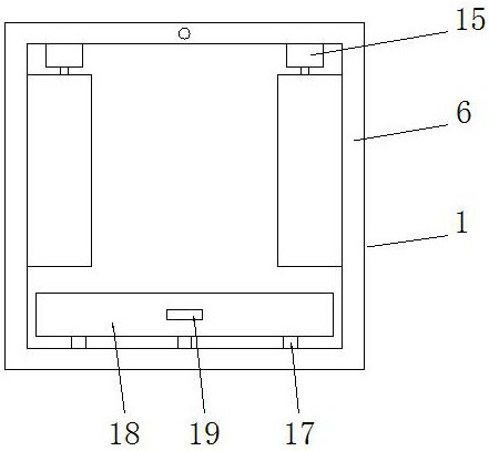
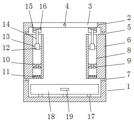
[0030] See Figure 1-2 , a PCB board welding station based on independent cooling technology, including a stand 1, the stand 1 is a rectangular ring frame structure, the top of the stand 1 is connected to a turning chamber 2, and a welding station is arranged in the turning chamber 2 plate 3, the welding platen 3 is rotatably connected to the inner cavity wall of the turning chamber 2 through the turning shaft 4, and the left and right sides of the platform 1 are symmetrically provided with side support chambers 5, and the inside of the side support chambers 5 A support column 6 is provided, and the support column 6 is rotatably connected to the side support cavity 5 through a rotating shaft 7. The lateral surface of the support column 6 is a semicircular structure, and the support column 6 is provided with an air cooling hole 8, and the air cooling hole 8 is arranged inside the support column 6. The cooling hole 8 connects the upper and lower end faces of the support column 6...

Embodiment 2

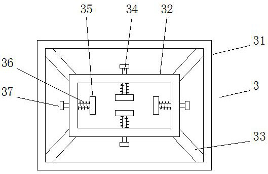
[0034] See image 3 The difference from Embodiment 1 is that the welding table 3 includes an outer frame 31 and an inner frame 32, the outer frame 31 is a rectangular ring frame structure, and the inner cavity of the outer frame 31 is provided with an inner plate frame 32, the inner frame 32 is a rectangular ring structure, the four corners of the inner frame 32 are fixedly connected to the inner cavity wall of the outer frame 31 through connecting rods 33, and the side walls of the inner frame 32 are embedded with Clamping rod 34, which is slidingly connected between the clamping rod 34 and the inner plate frame 32, one end of the clamping rod 34 is fixedly connected to the control panel 37, the other end of the clamping rod 34 is fixedly connected to the movable clamp 35, and the outer side of the clamping rod 34 is sleeved There is a pre-tension spring 36 matched with the movable clamp 35, the end of the pre-tension spring 36 is fixedly connected to the inner cavity wall of...

Embodiment 3

[0036] See Figure 4-5 The difference from Embodiment 1 is that the welding slag pumping box 18 includes a box body 181, and the two handles 19 are symmetrically arranged at the front and rear ends of the box body 181, and the middle part of the top of the box body 181 is provided with a welding slag Cavity 182, described welding slag cavity 182 corresponds to welding platen 3 on the vertical direction, is provided with isolation cavity 185 in the side wall of welding slag cavity 182, and described isolation cavity 185 is annular cavity, and the front and back of isolation cavity 185 The side ends are symmetrically connected to the air intake pipe 186, and the inner cavity of the air intake pipe 186 is provided with an air blowing fan 188 and a second protective net 187 in turn from the inside to the outside, and the air blowing fan 188 is fixedly connected to the air intake pipe 188 through a third fixed rod 189 On the inner cavity wall of the air intake pipe 186, the left an...


PUM


Abstract

The invention discloses a PCB welding table based on an independent cooling technology. The PCB welding table comprises a table frame; the top end of the table frame is connected with an overturning cavity in a communicating mode; a welding table plate is arranged in the overturning cavity; the welding table plate is rotationally connected to the inner cavity wall of the overturning cavity throughan overturning shaft; side supporting cavities are symmetrically formed in the left side end and the right side end of the table frame; supporting columns are arranged in the side supporting cavities; the supporting columns are rotationally connected to the side supporting cavities through rotating shafts; first protective nets, air cooling fans and pneumatic cylinders are sequentially arranged in inner cavities of air cooling holes from bottom to top; and supporting plate assemblies matched with the welding table plate are fixedly connected to the top ends of pneumatic rods on the pneumaticcylinders. External air is dragged by the air cooling fans to enter the air cooling holes and blows upwards along the air cooling holes, the rising airflow flows to the bottom end of the welding tableplate under the action of a flow guide cavity and obliquely blows the PCB on the welding table plate, thus the PCB can be rapidly cooled, the cooling time of the PCB can be greatly shortened, the non-machining time can be greatly shortened, and the machining efficiency can be greatly improved.

Description

technical field [0001] The invention relates to the technical field of welding stations, in particular to a PCB board welding station based on independent cooling technology. Background technique [0002] PCB, or printed circuit board, referred to as printed board, is one of the important components of the electronics industry. Almost every kind of electronic equipment, ranging from electronic watches and calculators to computers, communication electronic equipment, and military weapon systems, as long as there are electronic components such as integrated circuits, in order to make the electrical interconnection between various components, printed circuit boards must be used. plate. The printed circuit board is composed of an insulating base plate, connecting wires and pads for assembling and welding electronic components, and has the dual functions of a conductive line and an insulating base plate. [0003] Most of the PCB board welding can be completed by welding equipme...

Claims


Application Information

Patent Timeline
Patent Type & Authority Applications(China)
IPC IPC(8): B23K3/08B23K37/04B23K101/42
CPCB23K3/08B23K3/085B23K3/087B23K2101/42
Inventor 王文俊
Owner 王文俊
Why Eureka
Try Eureka