Furnace rear cover disassembling machine

A cover machine and furnace technology, applied in the field of automatic cover removal, can solve the problems of low work efficiency and high opening difficulty, and achieve the effect of high degree of automation and labor-saving operation.

Pending Publication Date: 2020-12-11
东莞松山智能机器人有限公司
View PDF0 Cites 6 Cited by
  • Summary
  • Abstract
  • Description
  • Claims
  • Application Information

AI Technical Summary

Problems solved by technology

Since the jig and PCBA board will be at high temperature after wave soldering, the current method is to manually open the jig to take out the PCBA board. This method is difficult to open. Due to the temperature relationship, it needs to be cooled before it can be operated, resulting in low work efficiency and other problems. there is a need to solve

Method used


Image

  • Furnace rear cover disassembling machine
  • Furnace rear cover disassembling machine
  • Furnace rear cover disassembling machine

Examples


Embodiment Construction

[0037] The present invention will be further described below in conjunction with the accompanying drawings.

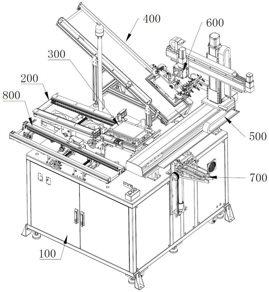
[0038] Such as Figure 1 to Figure 11 As shown, a cover removal machine after a furnace includes a frame 100, a feed conveying device 200 installed on the frame 100, a jig device 300 transmitted to the feed conveying device 200, a jig device 300 installed on the frame 100 and positioned at the feed conveyor The return device 400 on one side of the conveying device 200, the transmission device 500 installed on the frame 100, the reclaiming device 600 installed on the transmission device 500, and the material receiving device 700 installed on the frame 100 at one side of the transmission device 500, so The transmission device 500 drives the reclaiming device 600 and can be transmitted to the feeding conveying device 200 and the return device 400 .

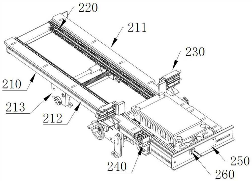
[0039] refer to Figure 2 ~ Figure 4 As shown, the feeding conveying device 200 includes a conveying bracket 210, a conve...


PUM


Abstract

The invention relates to the technical field of automatic cover disassembling, and particularly relates to a furnace rear cover disassembling machine. The furnace rear cover disassembling machine comprises a rack, a feeding conveying device installed on the rack, a jig device installed to the feeding conveying device, a backflow device installed on the rack and located on one side of the feeding conveying device, a transmission device installed on the rack, a material taking device installed on the transmission device and a material receiving device installed on the rack and located on one side of the transmission device, wherein the transmission device drives the material taking device to be in transmission with the feeding conveying device and the backflow device. According to the furnace rear cover disassembling machine, an automatic cover disassembling structure is adopted, a jig is positioned after backflow, the transmission device drives the material taking device to be in transmission with the jig position to disassemble an upper cover of the jig after positioning, a product piece can be taken out and placed on the material receiving device after disassembling, the upper cover of the jig and a jig base are taken by the material taking structure and then are placed to the backflow device for backflow, the overall automation degree is high, manual operation is saved, and continuous work in an assembly line manner can be achieved.

Description

technical field [0001] The invention relates to the technical field of automatic cover removal, in particular to a machine for removing the cover and removing the PCBA after a furnace. Background technique [0002] Automation technology is widely used in industry, agriculture, military, scientific research, transportation, commerce, medical care, services and households. The use of automation technology can not only liberate people from heavy physical labor, part of mental work, and harsh and dangerous working environments, but also expand human organ functions, greatly improve labor productivity, and enhance human ability to understand and transform the world. . Large-scale complete sets of equipment in the automation system, also known as automation devices. It refers to the process in which a machine or device is automatically operated or controlled according to a prescribed procedure or instruction without human intervention. [0003] Therefore, in the process of wave...

Claims


Application Information

Patent Timeline
Patent Type & Authority Applications(China)
IPC IPC(8): B23K1/08B23K3/08
CPCB23K1/085B23K3/08
Inventor 黄水灵彭心宽杨司再王善平
Owner 东莞松山智能机器人有限公司
Why Eureka
Try Eureka