Voltage control method for micro vibration motor driving chip
A voltage control method and driving chip technology, applied in the direction of linear DC motor control, etc., can solve problems such as single vibration effect, reduce input influence, increase adjustment range, and improve user experience.
- Summary
- Abstract
- Description
- Claims
- Application Information
AI Technical Summary
Problems solved by technology
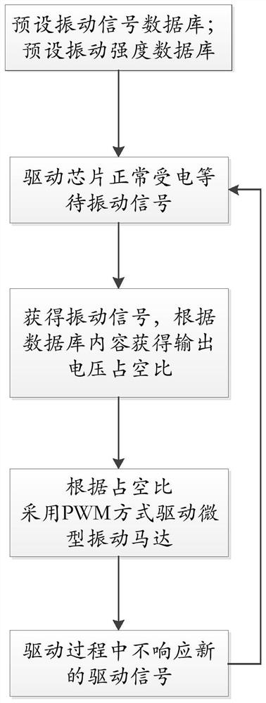
Method used
Image

Examples
Embodiment 1
[0041] In this embodiment, the preset usage scenario is a mobile phone terminal, the power supply voltage is rated at 3V DC power supply, and the starting voltage of the driver chip is 2.4V. The driver chip is connected with the micro-vibration motor, and the driver chip directly drives the micro-vibration motor to vibrate through the output voltage.
[0042] A vibration intensity database is preset in the driver chip. In this embodiment, five levels of vibration intensity 1 to 5 are preset, and the corresponding duty ratios are 20%, 40%, 60%, 80% and 100%. 100% of them are directly driving the micro vibration motor with 3V voltage.
[0043] The vibration signal database is preset in the driver chip. In this embodiment, the user defines A, B, C, D, E, and F signals, and sets: the vibration intensity of the A signal is level 1, and the vibration time is 0.25 S; B signal vibration intensity is level 2, vibration time is 0.25S; C signal vibration intensity is level 3, vibration ...
Embodiment 2
[0049] The difference between this embodiment and Embodiment 1 is that in the vibration signal database, there is also a signal X, which is defined as other undefined signals (ie default settings), the vibration intensity of signal X is 2, and the vibration time is 0.5S.
[0050] When a signal not defined in the vibration signal database appears, such as signal M, which is not defined in the vibration signal database, it will be automatically classified as signal X, and the driver chip will be driven according to the preset vibration information of the X signal vibration.
Embodiment 3
[0052] In this embodiment, the power supply voltage is 3.6V, and a vibration intensity database is preset in the driver chip. In this embodiment, the preset vibration intensity is 0-80, a total of 81 vibration levels. From low to high, the corresponding duty cycle is 10%, 11%...90%.
[0053] The vibration signal database is preset in the driver chip. In this embodiment, the user defines A, B, C, D, E, and F signals, and sets: the vibration intensity of the A signal is level 1, and the vibration time is 0.2 S; B signal vibration intensity is level 2, vibration time is 0.2S; C signal vibration intensity is level 3, vibration time is 0.2S; D signal vibration intensity is level 4, vibration time is 0.2S; E signal vibration intensity is 5 Level, vibration time is 0.25S; F signal vibration intensity is level 5, vibration time is 0.5S.
[0054] After completing the customization of the required parameters in the database, the power supply voltage directly supplies power to the drive...
PUM
 Abstract
Description
Claims
Application Information
 - R&D
- Intellectual Property
- Life Sciences
- Materials
- Tech Scout
- Unparalleled Data Quality
- Higher Quality Content
- 60% Fewer Hallucinations
Browse by: Latest US Patents, China's latest patents, Technical Efficacy Thesaurus, Application Domain, Technology Topic, Popular Technical Reports.
© 2025 PatSnap. All rights reserved.Legal|Privacy policy|Modern Slavery Act Transparency Statement|Sitemap|About US| Contact US: help@patsnap.com