Triangular control mechanism and its multi-station weaving method

A control mechanism and multi-station technology, applied in weft knitting, knitting, textiles and papermaking, etc., can solve the problems of long reciprocating stroke of the machine head, error of triangle action, affecting delivery time and cost, etc., to achieve a large increase in output , Eliminate the root cause of the failure and improve production efficiency

Active Publication Date: 2021-08-03
ZHEJIANG HAISEN KNITTING MACHINE TECHN
View PDF0 Cites 0 Cited by
  • Summary
  • Abstract
  • Description
  • Claims
  • Application Information

AI Technical Summary

Problems solved by technology

[0002] Existing triangular knitting systems for flat knitting machines such as gloves, socks, scarves, etc. have the following deficiencies: 1. Each triangular action is performed by multiple motors and electromagnets through connecting rods and other mechanisms. There are many parts such as brackets and brackets, and the structure of the triangular knitting system is complex, resulting in the defects of large size and heavy weight in the head of the flat knitting machine;
[0003] 2. Multiple electromagnets are installed in the moving machine head, which are easily affected by vibration and pollution and fail, resulting in errors in related triangular actions, resulting in pin strikes, difficult maintenance, and high maintenance costs;
[0004] 3. When repeating knitting, the needle selector still needs to pre-select each needle. The needle selector repeatedly selects needles, and the stitches repeatedly enter and exit the triangular track. Finally, select the needle for the next stroke, the reciprocating stroke of the machine head is long, the efficiency is low, and the speed is slow;
[0005] 4. In the past, all flat knitting machines used to weave the middle piece A (high position), tuck the H (middle position), and not weave B (low position). The needle, the needle selection piece is pushed from the low position to the high position by the push needle triangle, the top middle piece is pushed to the A (high) position, and then pressed back to the B (low) position by the needle clearing triangle, which will easily cause wear of the triangle and stitches, and it is easy to slip out missing pin phenomenon
[0006] In addition, the existing triangular knitting system controls the needle selection of the needle selection roller through the motor, which has the advantages of fast knitting speed, good stability, light force, and energy saving, but the disadvantage is that the needle selection roller can only perform one process, that is, Only one pattern can be woven. When changing the pattern, the steel pins need to be disassembled and rearranged, which requires high technical requirements and long working hours. Many enterprises can do nothing about it, which directly affects the delivery time and cost.
Therefore, most enterprises use one machine for one use. Limited by the volume of the drum, products with many changes and complexities cannot be arranged. If they need to make products with high added value, they need to buy more machines, which increases the cost of the enterprise and reduces the economic benefits.

Method used


Image

  • Triangular control mechanism and its multi-station weaving method
  • Triangular control mechanism and its multi-station weaving method
  • Triangular control mechanism and its multi-station weaving method

Examples


Embodiment 1

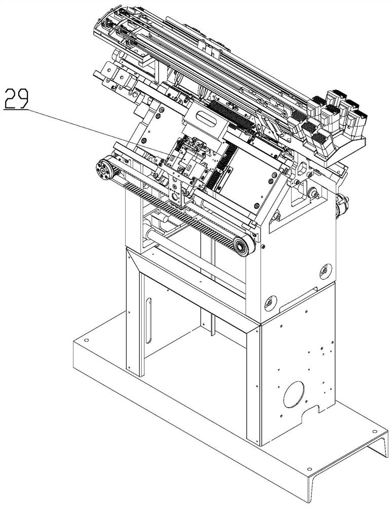
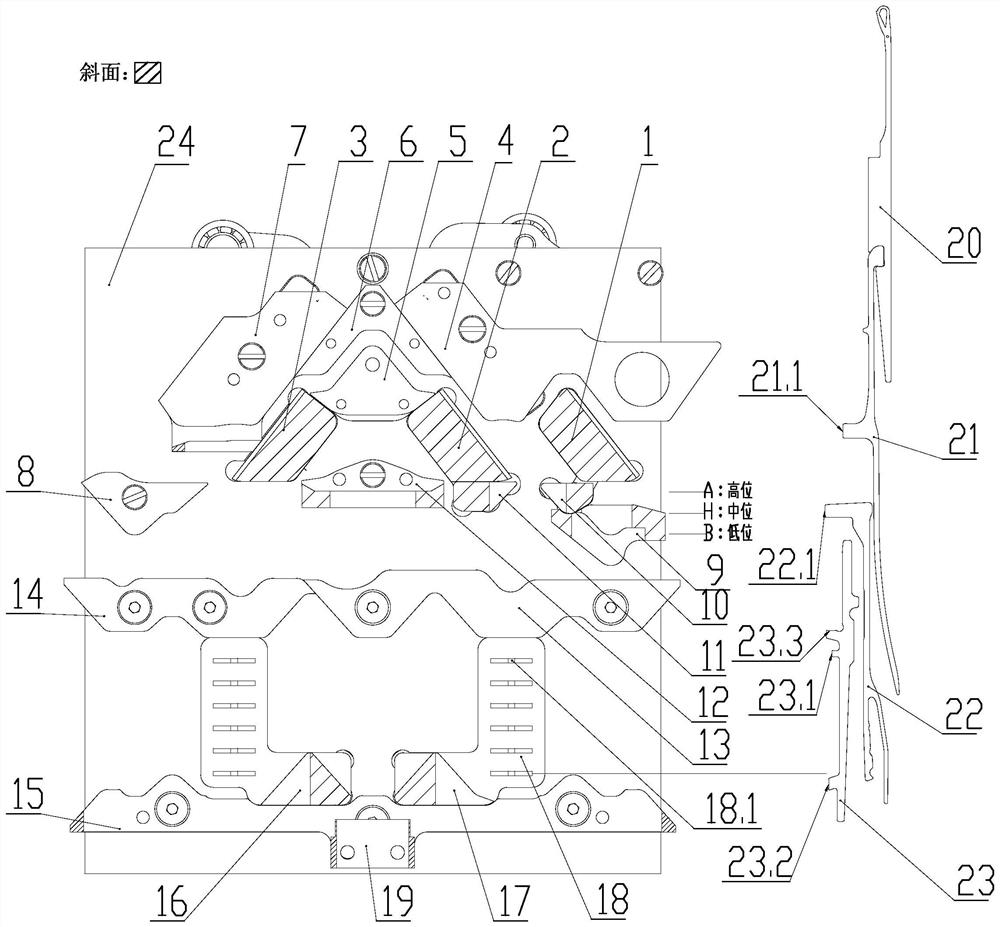
[0083] This embodiment proposes a triangular control mechanism, such as figure 2 As shown, the triangular control mechanism can be installed in such as figure 1 In the machine head 29 of the shown smart glove machine, the machine head 29 is symmetrically installed on the front and rear needle beds, and runs left and right. The machine head 29 described in this embodiment is unfolded by the rear machine head knitting system. The needle groups mentioned in the text are as figure 2 As shown on the right, it includes a needle jack 21, an intermediate piece 22, and a selector jack 23 from top to bottom. The needle jack 21 is nested on the crochet needle 20, and the needle movement is controlled by a triangular track (such as a knitting track, a tuck track) track, and can be pressed into the needle bed by the middle piece 22 and the cam; figure 2 As shown, A in the figure represents the high position, H represents the middle position, and B represents the low position), when ...

Embodiment 2

[0123] The principle of this embodiment is the same as that of Embodiment 1, the difference is that the needle selection homing triangle 19 of this embodiment is movable in translation, such as Figures 12 to 13 As shown, a slide bar 24.1 is provided on the triangular base plate 24, and one end of the needle selection homing cam 19 is located at the front of the triangular base plate 24 to realize the inductive effect of needle selection, and the other end is a translation block 19.3 located at the back of the triangular base plate 24, and the translation The block 19.3 is provided with a through hole for passing through the slide bar 24.1, the end of the slide bar 24.1 is fixed with a pin 19.4 and a spacer 19.7 to limit the translation block 19.3, and a spring is set between the spacer 19.7 and the translation block 19.3 24.2 Realize the reset of the moving block. The output shaft located in the needle selection area is provided with homing wheel 25.7. The cross section of tr...

Embodiment 3

[0125] The principle of this embodiment is the same as that of Embodiment 1, the difference is that the needle selection homing cam 19 of this embodiment is a swingable activity, such as Figures 14 to 16As shown, a homing wheel 25.7 is provided on the rotating shaft 25.1 located in the needle selection area. The needle selection homing cam 19 includes a rotating shaft 19.5 that is rotatably connected to the triangular bottom plate 24. The needle selection homing cam 19 is provided with a convex direction. The convex portion 19.6 of the homing wheel 25.7, the homing wheel 25.7 is provided with a groove 25.9 for accommodating the convex portion 19.6, the spring 24.2 on the needle selection homing cam 19 is a torsion spring sleeved on the rotating shaft 19.5, Through the rotating shaft 19.5, the needle selection homing cam 19 can swing between angles close to and away from the triangular bottom plate 24. Such as Figure 15 As shown, since the convex portion 19.6 does not corres...


PUM


Abstract

The invention relates to the knitting field of knitting technology, in particular to a cam control mechanism and its multi-station knitting method. A drive control mechanism is installed on the back of the triangular bottom plate, and a combined cam is fixed to control the action of the relevant cam components, and the motor rotates at an angle of combination. It is 1 station, the control is simple and reliable, and the number of controllable stations is large, avoiding the installation of multiple electromagnets in the moving machine head, eliminating the source of failure, making the machine head small in size, light in weight, high in reliability, and energy-saving. Electricity; through artificial intelligence control, it can be subdivided into multiple stations for knitting. Different knitting processes adopt specially set stations, and various modes can be switched flexibly, which greatly improves production efficiency. With the intelligent yarn feeder, it will provide artificial intelligence for future flat knitting machines. Point out a direction for innovation.

Description

technical field [0001] The invention relates to the knitting field of knitting technology, in particular to a cam control mechanism and a multi-station knitting method thereof. Background technique [0002] Existing triangular knitting systems for flat knitting machines such as gloves, socks, scarves, etc. have the following deficiencies: 1. Each triangular action is performed by multiple motors and electromagnets through connecting rods and other mechanisms. There are many parts such as brackets and brackets, and the structure of the triangular knitting system is complex, resulting in the defects of large size and heavy weight in the head of the flat knitting machine; [0003] 2. Multiple electromagnets are installed in the moving machine head, which are easily affected by vibration and pollution and fail, resulting in errors in related triangular actions, resulting in pin strikes, difficult maintenance, and high maintenance costs; [0004] 3. When repeating knitting, the ...

Claims


Application Information

Patent Timeline
IPC IPC(8): D04B15/36D04B1/10
CPCD04B1/102D04B15/36
Inventor 骆海生王涛
Owner ZHEJIANG HAISEN KNITTING MACHINE TECHN
Why Eureka
Try Eureka