
Q-switched cavity dumped sub-nanosecond laser

A laser oscillator, laser energy technology, used in lasers, laser parts, laser surgery, etc., can solve the problem of complex and expensive treatment or removal of tattoos and other pigmentation

Pending Publication Date: 2020-12-04
赛诺秀有限公司
View PDF7 Cites 0 Cited by
  • Summary
  • Abstract
  • Description
  • Claims
  • Application Information

AI Technical Summary

Problems solved by technology

Unfortunately, current systems of such short pulse duration and high energy output may be too complex and / or expensive to treat or remove tattoos and other hyperpigmentation

Method used


Image

  • Q-switched cavity dumped sub-nanosecond laser
  • Q-switched cavity dumped sub-nanosecond laser
  • Q-switched cavity dumped sub-nanosecond laser

Examples


Embodiment

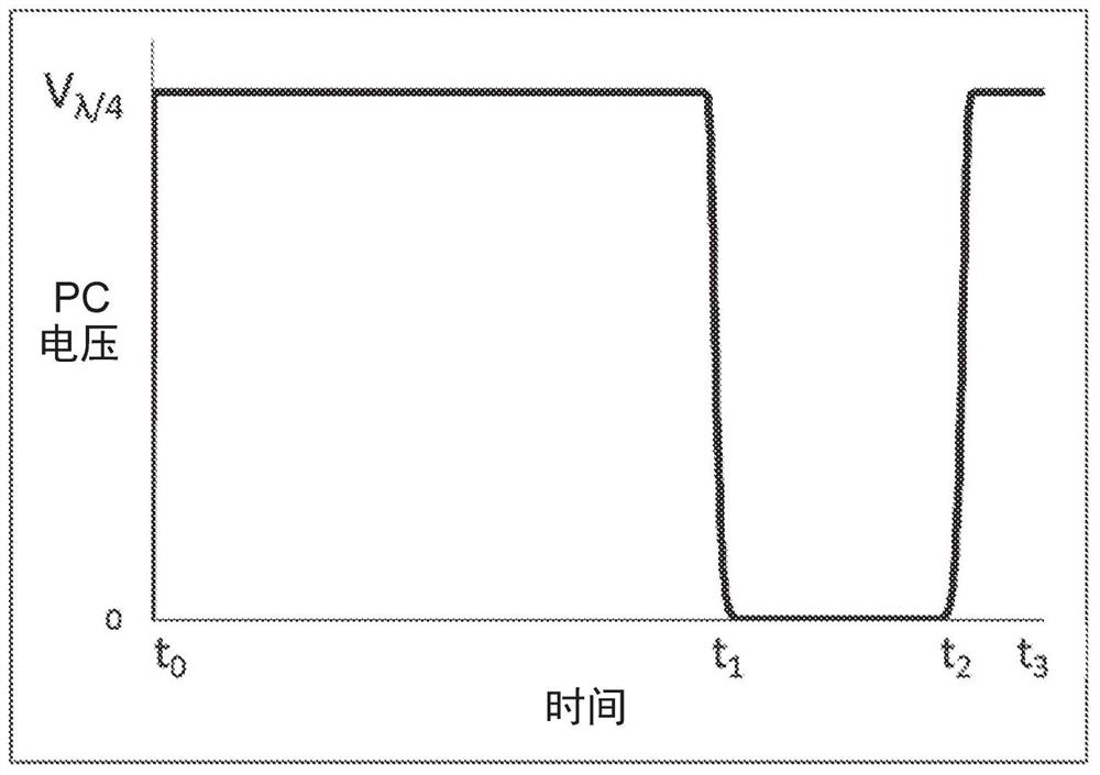
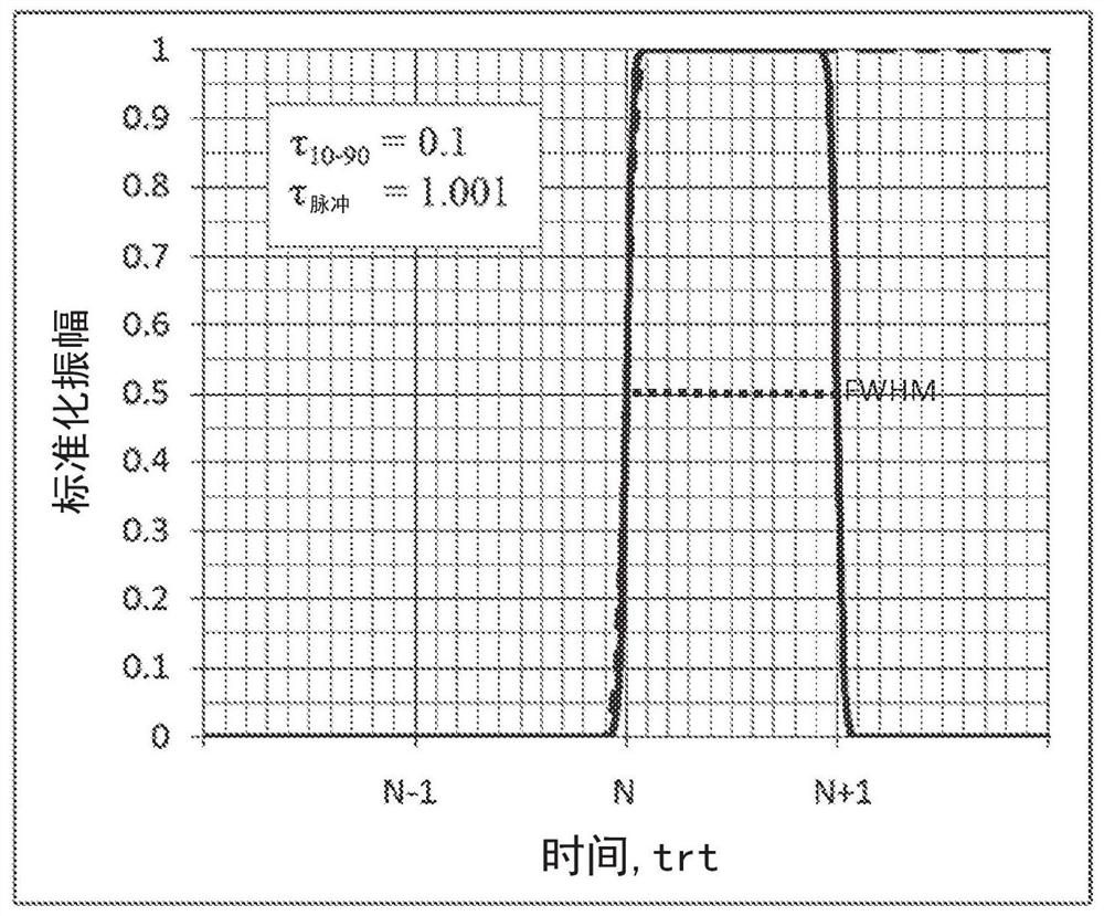
[0141] Aspects of the present disclosure relate to a laser oscillator for generating laser energy with a pulse duration of less than 1 nanosecond. The laser oscillator includes (a) a first reflective mirror and a second reflective mirror within a housing, wherein the first reflective mirror and the second reflective mirror are along an axis between the first reflective mirror and the second reflective mirror providing sub-nanosecond round-trip times for laser radiation; (b) an electro-optical device, a polarizer, and a lasing medium positioned along the axis between the first mirror and the second mirror; (c) a pump source, operatively coupled to the lasing medium; and (d) wherein the laser oscillator is capable of traveling through at least three consecutive states including stall, accumulation, and cavity dump. According to one aspect, the cavity dump state has an acceptable transient time range that is greater than the ideal step function transient time. According to one a...


PUM

PropertyMeasurementUnit
diameteraaaaaaaaaa
diameteraaaaaaaaaa
diameteraaaaaaaaaa

Abstract

Apparatuses and methods are disclosed for applying laser energy having desired pulse characteristics, including a sufficiently short duration and / or a sufficiently high energy for the photomechanicaltreatment of skin pigmentations and pigmented lesions, both naturally-occurring (e.g., birthmarks), as well as artificial (e.g., tattoos). The laser energy may be generated with an apparatus having aresonator with a sub-nanosecond round trip time.

Description

[0001] relevant application data [0002] This application claims priority to U.S. Patent Application No. 62 / 635,174, filed February 26, 2018, and U.S. Patent Application No. 62 / 653,767, filed April 6, 2018, which, for all purposes, Each of which is hereby incorporated by reference in its entirety. technical field [0003] The present disclosure relates to devices and methods for delivering laser energy with short pulse durations (eg, less than about 1 nanosecond) and high energy output per pulse (eg, greater than about 100 millijoules). The desired operating parameters are achieved in part by a laser configuration including a laser cavity designed with sub-nanosecond round trip times in order to produce output pulse durations in the sub-nanosecond range. This laser configuration also includes Q-switched and cavity dumped features. As a result, relatively simple devices can be used to generate laser energy suitable for a variety of applications, including cosmetic and medica...

Claims


Application Information

Patent Timeline
Patent Type & Authority Applications(China)
IPC IPC(8): H01S3/09H01S3/10
CPCH01S3/08054H01S3/08H01S3/115H01S3/1103H01S3/08059H01S3/1075H01S3/1623H01S3/1633H01S3/0941H01S3/094057H01S3/061H01S3/093H01S3/042H01S3/0407A61B18/203A61B2017/00756A61B2017/00769A61B2017/00154A61B2018/00458A61B2018/20553A61B2018/00571A61F9/00825A61B18/20A61F2009/00863A61B2018/00404A61B2018/00452G02F1/03H01S3/1127H01S3/1312H01S3/1643
Inventor M·米尔科夫H·曾兹
Owner 赛诺秀有限公司
Learn More