High-impedance combined transformer

A combined transformer and high-impedance technology, applied in the field of distribution transformers, can solve the problems of high cost, difficulty in disassembly and installation, and low efficiency, and achieve the effect of convenient assembly and disassembly, convenient maintenance and replacement, and improved maintenance efficiency

Pending Publication Date: 2020-12-04
合肥鑫伟电力设备有限公司
View PDF8 Cites 0 Cited by
  • Summary
  • Abstract
  • Description
  • Claims
  • Application Information

AI Technical Summary

Problems solved by technology

[0004] The transformer in this patent also has the following disadvantages: 1. In the process of installation and maintenance of the transformer, hands must be inserted into the interior for operation, which is very inconvenient and affects the efficiency of installation and maintenance of the transformer, and the transformer is integrated, so it is not easy to disassemble and install ; 2. The staff cannot know the internal temperature of the transformer, and if they open the transformer rashly, it will cause certain dangers; 3. The transformer adopts a high-voltage built-in method to achieve the purpose of high impedance, which is too expensive and not easy to use; 4. When the transformer is in use, the straight cylindrical iron core will generate a lot of noise, and there will be magnetic flux leakage inside, and the efficiency is low

Method used


Image

  • High-impedance combined transformer
  • High-impedance combined transformer
  • High-impedance combined transformer

Examples


Embodiment Construction

[0024] The following will clearly and completely describe the technical solutions in the embodiments of the present invention with reference to the accompanying drawings in the embodiments of the present invention. Obviously, the described embodiments are only some, not all, embodiments of the present invention. Based on the embodiments of the present invention, all other embodiments obtained by persons of ordinary skill in the art without making creative efforts belong to the protection scope of the present invention.

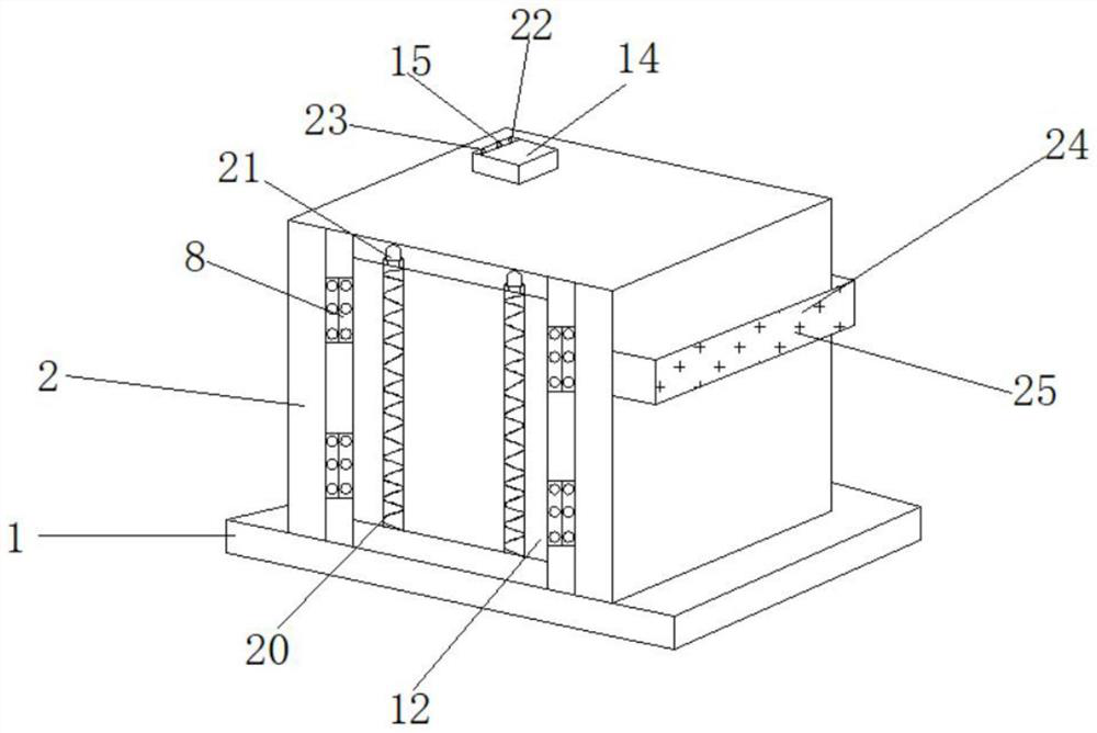
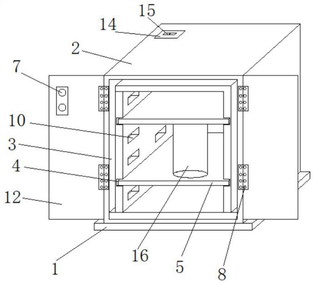
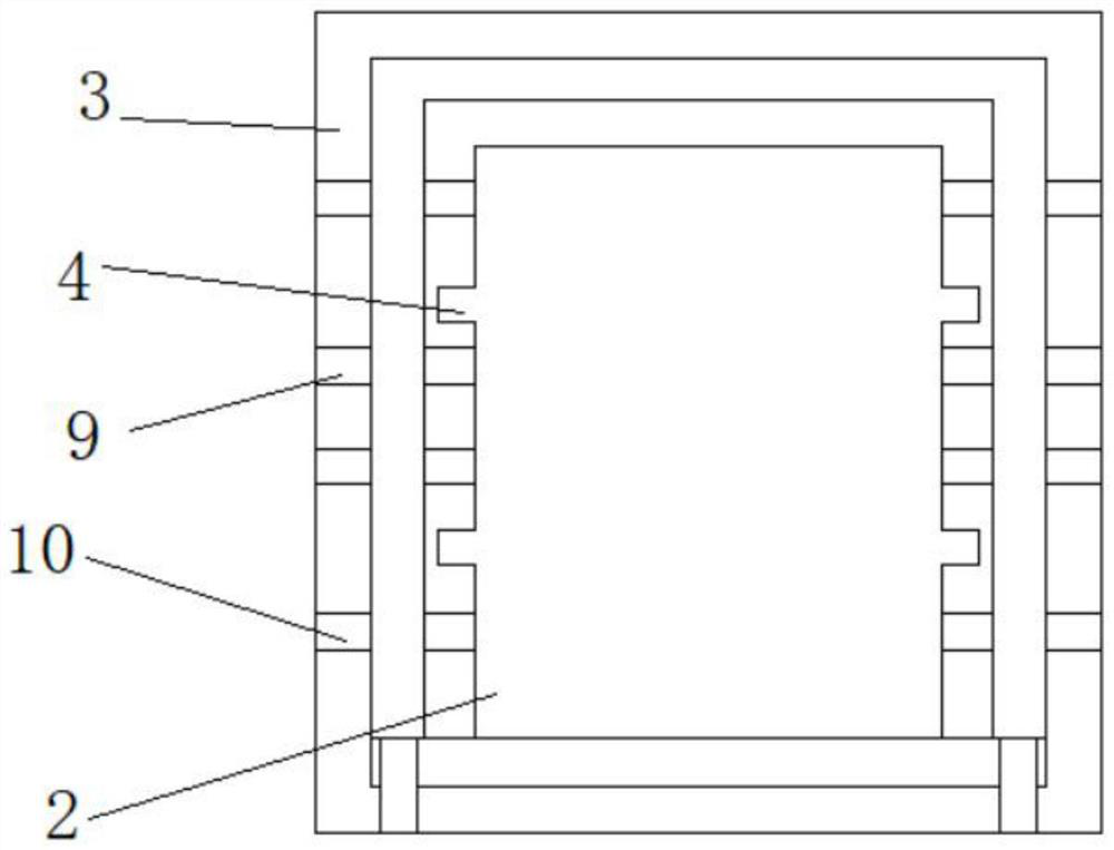
[0025] see Figure 1-5 , the present invention provides a technical solution: a high-impedance combined transformer, including a base 1, an outer cabinet 2 and an inner cabinet 3 are fixedly connected to the inside of the base 1, and the top of the outer cabinet 2 is fixedly provided with A temperature display screen 15, and a control switch A14 is fixedly installed on the outer top of the outer cabinet body 2, a control switch B22 is fixedly installed on the ...


PUM


Abstract

The invention discloses a high-impedance combined transformer, and belongs to the technical field of transformers. The high-impedance combined transformer is characterized in that an outer cabinet body and an inner cabinet body are fixedly connected to the inner side of a base, a temperature display screen is fixedly arranged at the top of the outer cabinet body, a control switch A is fixedly mounted at the top end of the outer side of the outer cabinet body, and a control switch B is fixedly mounted at the lower end of the outer side of the control switch A. During normal use, the two sides of a sliding plate are aligned with inserting grooves in the inner side wall of the inner cabinet body and inserted into the inserting grooves so as to insert the sliding plate into the inner cabinet body, and at the moment, electronic components and the like are placed in the inner cabinet body to be normally used; and when the electronic components and the like in the transformer need to be overhauled and replaced, the sliding plate can be pulled out of the inner cabinet body only by pulling the sliding plate towards the side away from the inner cabinet body along the inserting groove, and atthe moment, the electrical components on the surface of the vertical plate move out of the inner cabinet body and are not limited by the specification of the inner cabinet body any more, so that theelectrical components outside the inner cabinet body are convenient to overhaul and replace.

Description

technical field [0001] The invention relates to the technical field of distribution transformers, in particular to a high-impedance combined transformer. Background technique [0002] The transformer is a device that uses the principle of electromagnetic induction to change the AC voltage. The main components are the primary coil, the secondary coil and the iron core (magnetic core). The main functions are: voltage conversion, current conversion, impedance conversion, isolation, voltage stabilization (magnetic Saturated transformers), etc., can be divided into: power transformers and special transformers (electric furnace transformers, rectifier transformers, power frequency test transformers, voltage regulators, mining transformers, audio transformers, intermediate frequency transformers, high frequency transformers, impact transformers, instrument with transformers, electronic transformers, reactors, transformers, etc.). [0003] For example, the patent application public...

Claims


Application Information

Patent Timeline
Patent Type & Authority Applications(China)
IPC IPC(8): H01F27/02H01F27/24H01F27/28H01F27/30H01F27/33H01F27/34H01F27/40
CPCH01F27/022H01F27/40H01F27/402H01F27/34H01F27/2895H01F27/24H01F27/306H01F27/33H01F27/346H01F2027/406
Inventor 周伟
Owner 合肥鑫伟电力设备有限公司
Why Eureka
Try Eureka