
Dehumidification and cooling independent control system and dehumidification and cooling method

An independent control and auxiliary machine technology, applied in the field of dehumidification and cooling in the workshop, can solve the problems of ineffective control of temperature and humidity, lower air temperature, and disproportionate changes, and achieve good use effect, lower air temperature, and reasonable structure.

Pending Publication Date: 2020-12-04
淮安市伟杰配电控制设备有限公司
View PDF7 Cites 4 Cited by
  • Summary
  • Abstract
  • Description
  • Claims
  • Application Information

AI Technical Summary

Problems solved by technology

However, in the prior art, the dehumidification process is generally that the air is condensed into water vapor after being heat-exchanged by the evaporator in the dehumidifier, and then the water vapor is separated to achieve dehydration. In this process, the moisture is discharged more thoroughly, resulting in dry air; In the process of water vapor, a large amount of cooling capacity reduces the air temperature, and the temperature and humidity change out of proportion. At this time, the temperature and humidity cannot be effectively controlled. Now there is an urgent need for an independent control system for dehumidification and cooling and a dehumidification and cooling method to solve the above problems.

Method used


Image

  • Dehumidification and cooling independent control system and dehumidification and cooling method
  • Dehumidification and cooling independent control system and dehumidification and cooling method
  • Dehumidification and cooling independent control system and dehumidification and cooling method

Examples


Embodiment Construction

[0035] In order to make the technical means, creative features, goals and effects achieved by the present invention easy to understand, the present invention will be further described below in conjunction with specific embodiments.

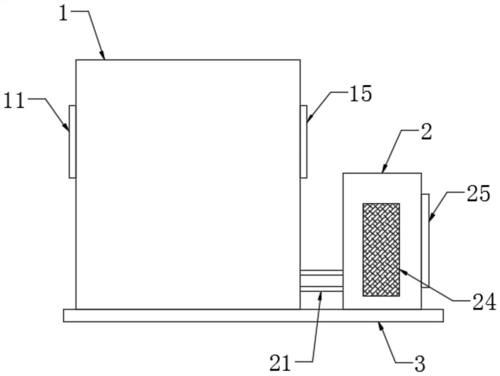
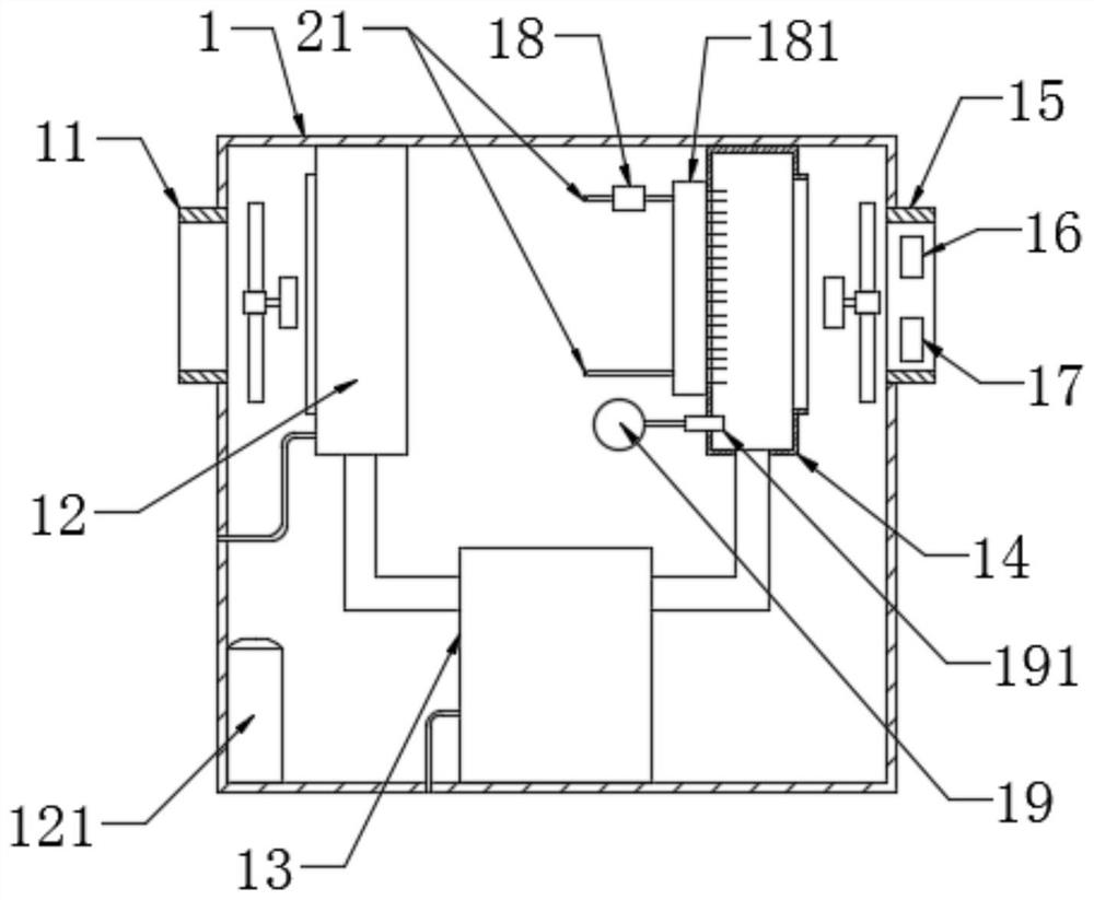
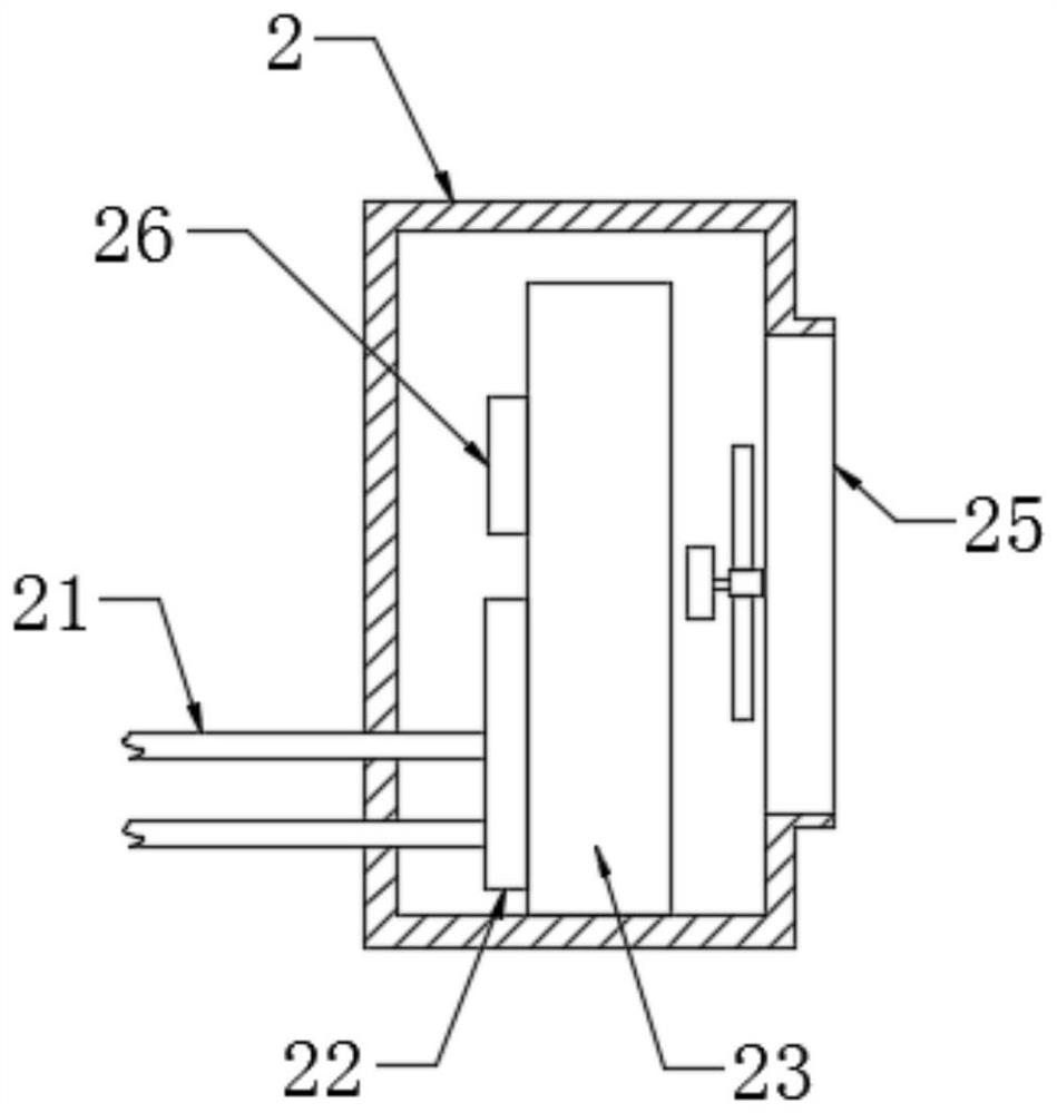
[0036] see Figure 1-Figure 5 , the present invention provides a technical solution: an independent control system for dehumidification and cooling, including a main machine 1, an auxiliary machine 2, a bottom bracket 3, a dehumidification and cooling system, a temperature and humidity adjustment system, and an independent temperature and humidity control system, and the upper side of the bottom bracket 3 is installed There are host 1 and slave 2;

[0037] The dehumidification and cooling system includes an air inlet 2, an evaporator 12, a compressor 121, a steam-water separator 13, an air outlet 15, a condenser 23, and an expansion valve 26. The left and right sides of the host 1 are respectively provided with an air inlet 2 and an air outlet. p...


PUM


Abstract

The invention provides a dehumidification and cooling independent control system and a dehumidification and cooling method. The dehumidification and cooling independent control system comprises a mainmachine, an auxiliary machine, a bottom support, a dehumidification and cooling system, a temperature and humidity adjusting system and a temperature and humidity independent control system; the mainmachine and the auxiliary machine are installed on the upper side of the bottom support; the temperature and humidity independent control system comprises a single-chip microcomputer, a temperature setting module, a humidity setting module, a temperature sensor, a humidity sensor, a circulating pump control circuit and an electric throttle valve control circuit, wherein the temperature sensor andthe humidity sensor are arranged at the exhaust port, and the temperature setting module and the humidity setting module are connected with the single-chip microcomputer; the single-chip microcomputer is connected with an electric throttle valve through the throttle valve control circuit; and the single-chip microcomputer is connected with a circulating pump through the circulating pump control circuit. The dehumidification and cooling independent control system provided by the invention is reasonable in structure, capable of independently controlling air dehumidification and cooling and goodin using effect.

Description

technical field [0001] The invention relates to an independent control system for dehumidification and cooling and a method for dehumidification and cooling, which belong to the field of dehumidification and cooling in workshops. Background technique [0002] The current dehumidifier generally consists of a compressor, an evaporator, a condenser, a fan, and a temperature and humidity control system. The working principle is that the fan generally sucks humid air into the machine and passes through a heat exchanger. At this time, the moisture in the air is condensed into water. Beads, the treated dry air is discharged outside the machine, and such a cycle reduces the indoor humidity. However, in the prior art, the dehumidification process is generally that the air is condensed into water vapor after being heat-exchanged by the evaporator in the dehumidifier, and then the water vapor is separated to achieve dehydration. In this process, the moisture is discharged more thorough...

Claims


Application Information

Patent Timeline
IPC IPC(8): F24F3/14F24F6/14F24F11/54F24F11/64F24F11/84F24F110/20
CPCF24F3/14F24F6/14F24F11/54F24F11/64F24F11/84F24F2110/20
Inventor 廖勇波郭跃
Owner 淮安市伟杰配电控制设备有限公司
Learn More