
Semiconductor structure and preparation method thereof

A technology of semiconductor and wire layer, which is applied in the field of semiconductor structure and its preparation, and can solve problems such as poor contact, affecting the life of the probe, and damage

Active Publication Date: 2020-12-01
晶芯成(北京)科技有限公司
View PDF1 Cites 1 Cited by
  • Summary
  • Abstract
  • Description
  • Claims
  • Application Information

AI Technical Summary

Problems solved by technology

[0002] At present, in the redistribution layer structure of the prior art, after the trench is formed, a metal layer is deposited into the trench. However, after the metal layer is deposited, there is a notch at the top opening of the trench. The pores described in this paper, so that, on this basis, other semiconductor layers are deposited, and when the through holes for the insertion of the probes during the wafer electrical test (wafer acceptance test, WAT) are formed, the through holes will be Impurities remain on the sidewall of the wafer, and the remaining impurities will damage the tip of the probe used in the wafer electrical test (wafer acceptance test, WAT), thus affecting the life of the probe
In the subsequent packaging process, the residue of impurities will also lead to poor contact

Method used


Image

  • Semiconductor structure and preparation method thereof
  • Semiconductor structure and preparation method thereof
  • Semiconductor structure and preparation method thereof

Examples


Embodiment Construction

[0058] Embodiments of the present invention are described below through specific examples, and those skilled in the art can easily understand other advantages and effects of the present invention from the content disclosed in this specification. The present invention can also be implemented or applied through other different specific embodiments, and various modifications or changes can be made to the details in this specification based on different viewpoints and applications without departing from the spirit of the present invention.

[0059] It should be noted that the diagrams provided in this embodiment are only schematically illustrating the basic idea of ​​the present invention, and only the components related to the present invention are shown in the diagrams rather than the number, shape and shape of the components in actual implementation. Dimensional drawing, the type, quantity and proportion of each component can be changed arbitrarily during actual implementation, ...


PUM

PropertyMeasurementUnit
Thicknessaaaaaaaaaa
Thicknessaaaaaaaaaa

Abstract

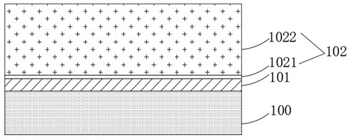
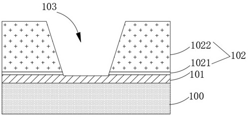
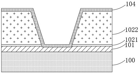
The invention discloses a semiconductor structure and a preparation method thereof. The semiconductor structure comprises a substrate; a conducting wire layer positioned on the substrate; a dielectriclayer located on the conducting wire layer; a groove located in the dielectric layer, wherein the bottom end of the groove is connected with the conducting wire layer, and the side wall of the groovehas an inclination angle; a barrier layer located on the dielectric layer and the conducting wire layer at the bottom end of the groove; a metal layer positioned in the groove and on the barrier layer; a plurality of protective layers on the metal layer; and through holes positioned in the plurality of protective layers. According to the invention, the condition that impurities remain on the sidewall of the through hole can be effectively improved, so that the damage to the probe can be effectively reduced during the wafer electrical property test.

Description

technical field [0001] The invention relates to the technical field of semiconductors, in particular to a semiconductor structure and a preparation method thereof. Background technique [0002] At present, in the redistribution layer structure of the prior art, after the trench is formed, a metal layer is deposited into the trench. However, after the metal layer is deposited, there is a notch at the top opening of the trench. The pores described in this paper, so that, on this basis, other semiconductor layers are deposited, and when the through holes for the insertion of the probes during the wafer electrical test (wafer acceptance test, WAT) are formed, the through holes will be Impurities remain on the sidewall of the wafer, and the remaining impurities will damage the tip of the probe used in the wafer electrical test (wafer acceptance test, WAT), thus affecting the life of the probe. In the subsequent packaging process, the residue of impurities will also lead to poor ...

Claims


Application Information

Patent Timeline
IPC IPC(8): H01L23/522H01L23/528H01L21/768
CPCH01L21/76816H01L21/76877H01L23/5226H01L23/5283
Inventor 张国伟周儒领吴佳特
Owner 晶芯成(北京)科技有限公司
Learn More