Fixing device and image forming apparatus
A technology for fixing belts and fixing parts, applied in the direction of electrical recording technology using charge graphics, equipment and instruments using electrical recording technology using charge graphics, etc., capable of solving problems such as lubricating performance degradation of lubricating oil
- Summary
- Abstract
- Description
- Claims
- Application Information
AI Technical Summary
Problems solved by technology
Method used
Image
Examples
Embodiment approach 1
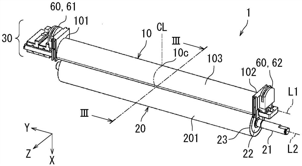
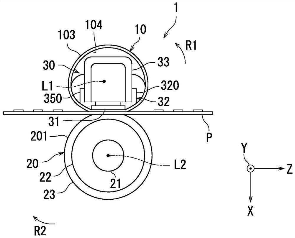
[0023] Hereinafter, Embodiment 1 of the present invention will be described with reference to the drawings. In addition, the same reference numerals are used for the same or corresponding parts in the drawings, and the description thereof will not be repeated. In addition, in the first embodiment, the X-axis, Y-axis and Z-axis that are orthogonal to each other are drawn in the figure. The Z axis is parallel to the vertical plane, and the X and Y axes are parallel to the horizontal plane.
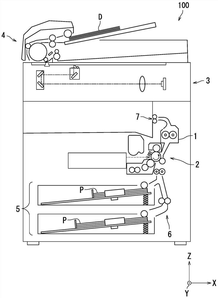
[0024] refer to figure 1 , the image forming apparatus 100 according to Embodiment 1 of the present invention will be described. figure 1 This is the image forming apparatus 100 according to the first embodiment. The image forming apparatus 100 is, for example, a copying machine, a facsimile machine, or a multifunction machine having these functions. In Embodiment 1, the image forming apparatus 100 is a monochrome multifunctional machine.
[0025] Such as figure 1 As shown, the image f...
Embodiment approach 2
[0089] Next, in Figure 1 to Figure 8 also refer to Figure 9 , the image forming apparatus 100 according to Embodiment 2 will be described. Figure 9 It is the fixing device 1 of the image forming apparatus 100 according to Embodiment 2 viewed from the Z-axis positive side.
[0090] In the second embodiment, the inclined slit 35s is provided on the first side surface 320 of the heater fixing member 32 included in the fixing device 1 of the image forming apparatus 100 , and the inclined slit 35s is arranged on the first rotation axis L1 of the fixing belt 10 . direction (first end 321, first end 351, second end 323, second end 353) to the end region (end region 11, end area 12).
[0091] Such as Figure 9 As shown, the fixing device 1 has an end region 11 and an end region 12. The end region 11 extends from the first end 321 of the fixing belt 10 included in the fixing belt 10 to the boundary line 14 on the way to the center 10c. The upper region 12 extends from the secon...
Embodiment approach 3
[0101] Next, in Figure 1 to Figure 8 also refer to Figure 10 , Figure 11 (a) and Figure 11 (b) The image forming apparatus 100 according to the third embodiment will be described. Figure 10 It is the fixing device 1 of the image forming apparatus 100 according to Embodiment 3 viewed from the Z-axis positive side. Figure 11 (a) and Figure 11 (b) is Figure 10 Enlarged view of A1 and A2 in.
[0102] In Embodiment 3, in the fixing device 1 of the image forming apparatus 100 , the inclination angle θ of the inclined slit 35 s with respect to the first rotation axis L1 is measured from the end portion (the first end portion) of the fixing belt 10 in the direction of the first rotation axis L1 . 321, the first end portion 351, the second end portion 323, and the second end portion 353) gradually become larger toward the center 10c.
[0103] Such as Figure 10 As shown, the fixing device 1 has an end region 11 and an end region 12. The end region 11 extends from the fi...
PUM
 Abstract
Description
Claims
Application Information
 - Generate Ideas
- Intellectual Property
- Life Sciences
- Materials
- Tech Scout
- Unparalleled Data Quality
- Higher Quality Content
- 60% Fewer Hallucinations
Browse by: Latest US Patents, China's latest patents, Technical Efficacy Thesaurus, Application Domain, Technology Topic, Popular Technical Reports.
© 2025 PatSnap. All rights reserved.Legal|Privacy policy|Modern Slavery Act Transparency Statement|Sitemap|About US| Contact US: help@patsnap.com


