
Shell of illuminating device and manufacturing method thereof and illuminating device with shell

A technology for a lighting device and a manufacturing method, which is applied to the cooling/heating device of the lighting device, the parts of the lighting device, the damage prevention measures of the lighting device, etc., and can solve the problem of loose clamping, poor sealing effect, and extrusion of the sealing ring The degree of inconsistency and other problems, to achieve the effect of reducing the number

Inactive Publication Date: 2013-03-20
OSRAM GMBH
View PDF4 Cites 0 Cited by
  • Summary
  • Abstract
  • Description
  • Claims
  • Application Information

AI Technical Summary

Problems solved by technology

However, since the two housing parts are fastened together or fixed together by fastening bolts, the compression degree of the sealing ring at different positions between the housing parts is inconsistent, and in some places it may The clamping is tight, and some places may be looser
In the place where the clamping is looser, the sealing effect may be poor, and water and dust may enter the interior of the housing from this position, resulting in damage to the internal LED lighting components.

Method used


Image

  • Shell of illuminating device and manufacturing method thereof and illuminating device with shell
  • Shell of illuminating device and manufacturing method thereof and illuminating device with shell
  • Shell of illuminating device and manufacturing method thereof and illuminating device with shell

Examples


Embodiment Construction

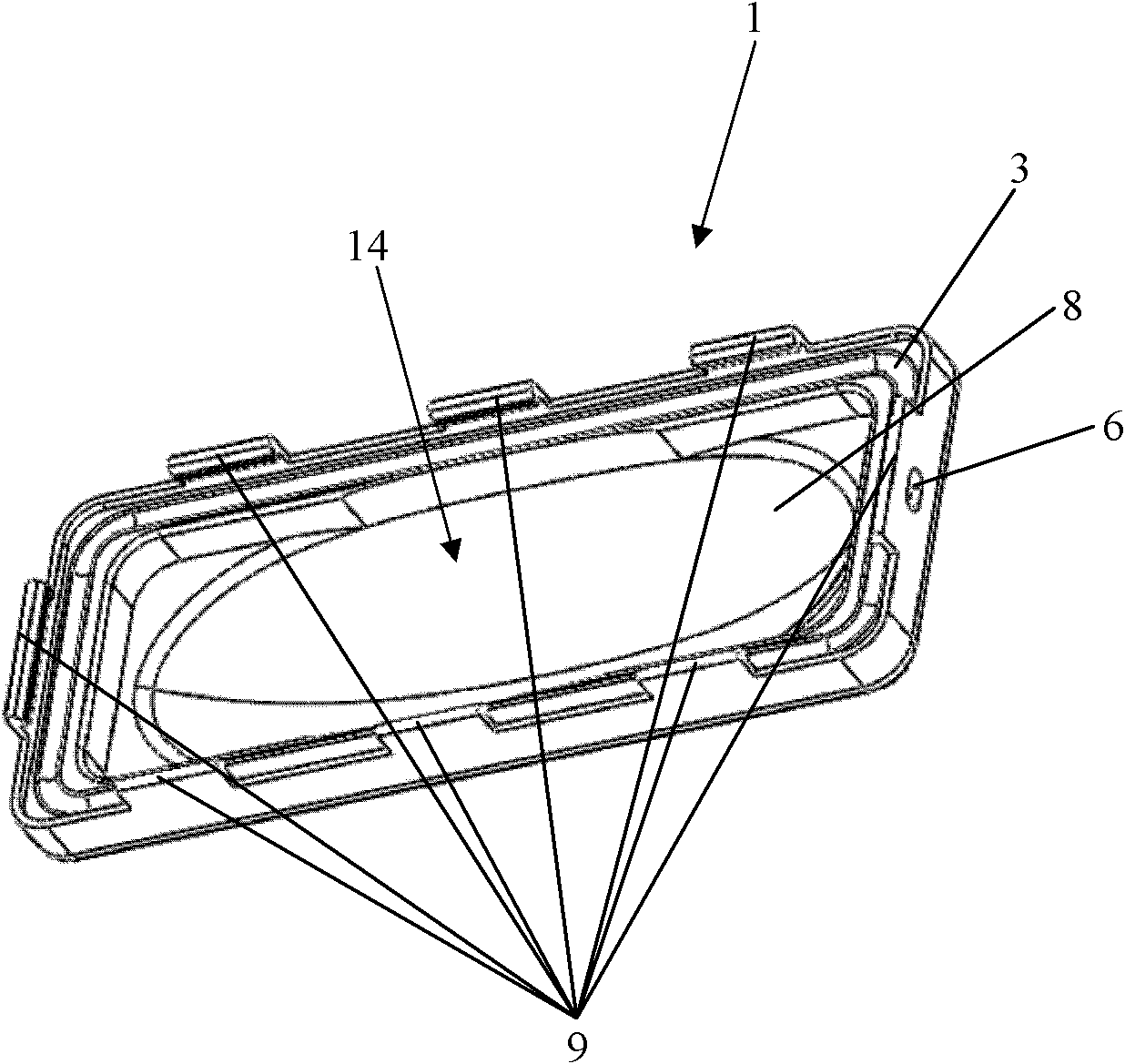
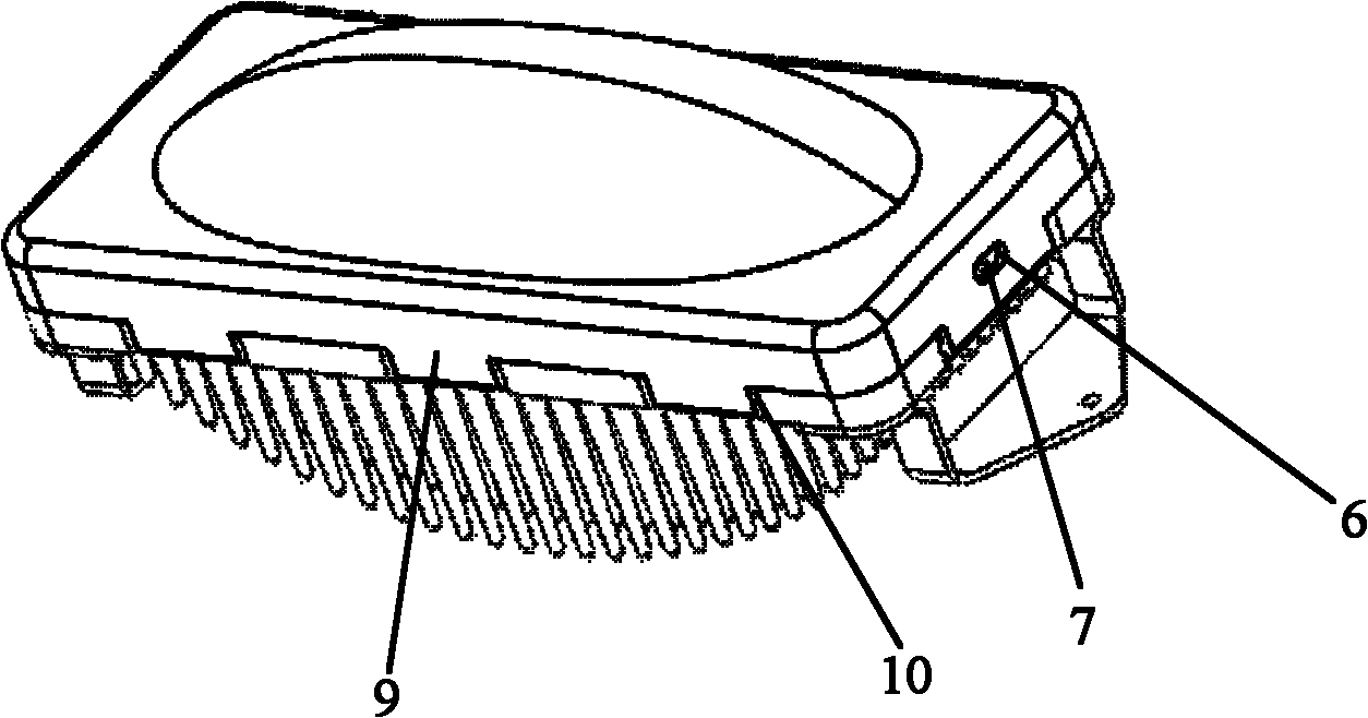
[0025] figure 1 A schematic diagram of the upper housing part 1 of the housing according to the present invention is shown, as can be seen from the figure, the upper housing part 1 has a top surface designed as a light-transmitting cover 8 and four vertically protruding from the top surface. side walls, these sides jointly define the assembly cavity 14. Additionally, from figure 1 As can be seen in the figure, first grooves 3 extending on each end surface are formed on the end surfaces of the four side walls. Meanwhile, hooks 9 are also formed on the four side walls. In the design solution of the present invention, the transparent cover 8 can be made of transparent glass or plastic. In addition, in figure 1 It can also be seen in the figure that an injection hole 6 leading into the filling channel 5 is also formed on the upper casing part 1 for filling the potting compound 16 into the casing through the injection hole 6 .

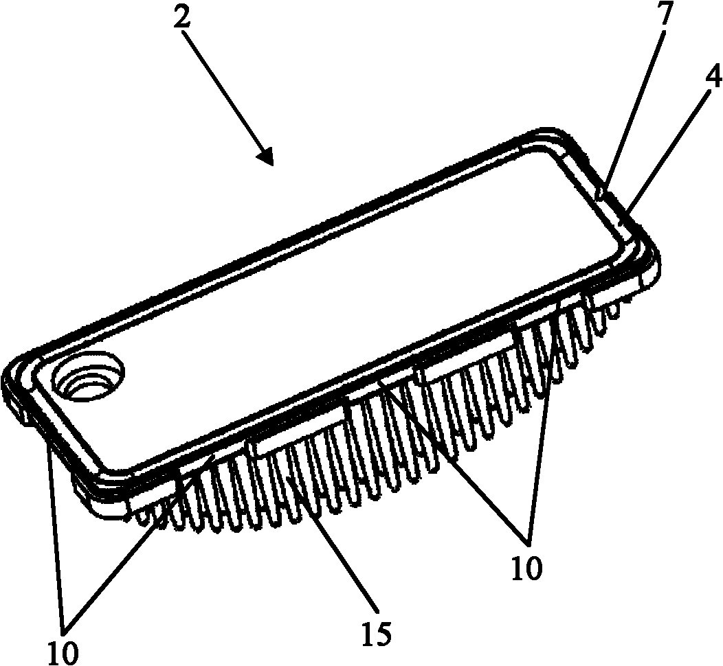
[0026] figure 2 A schematic view of the lower ...


PUM


Abstract

The invention relates to a shell used for an illuminating device which comprises an upper shell portion (1) and a lower shell portion (2) which are assembled together by use of respective contact surfaces and form an assembly cavity (14). A first groove (3) and a second groove (4) are formed in the respective contact surfaces of the upper shell portion (1) and the lower shell portion (2). A filling channel (5) surrounding the assembly cavity (4) is formed by the combination of the first groove (3) and the second groove (4).The filling channel (5) is filled with liquid congealable pouring sealant (16). The invention further relates to an illuminating device with the shell and a manufacturing method of the shell used for the illuminating device.

Description

technical field [0001] The invention relates to a casing for an illuminating device and a manufacturing method thereof. Furthermore, the present invention also relates to a lighting device having the housing of the above type. Background technique [0002] With the continuous improvement of material and cultural living standards, more and more people choose to go out at night to participate in various activities. Therefore, well-lit streets are becoming more and more important. In addition, with the continuous development of LED chip technology, more and more people use LEDs as light sources in street lamps for illuminating streets. However, since the street lamp is used in an outdoor environment, it is required that the shell of the street lamp has good waterproof and dustproof performance. [0003] In the prior art, the housing of a street lamp is usually composed of an upper housing part and a lower housing part. These two housing parts are fastened together to form a ...

Claims


Application Information

Patent Timeline
Patent Type & Authority Applications(China)
IPC IPC(8): F21V31/04F21V29/00F21V17/16F21S2/00F21Y101/02
CPCF21V31/03F21V29/225F21Y2105/001F21V31/005F21V31/04F21V15/01F21Y2101/02F21V7/0083F21V29/763F21W2131/103F21Y2105/10F21Y2115/10
Inventor 何源源袁海平冯耀军何玉宝
Owner OSRAM GMBH
Learn More