
Disc brake lubricating system and manufacturing method thereof

A disc brake and lubrication system technology, applied in the direction of brake type, brake parts, engine lubrication, etc., can solve the problems of increased clearance, increased maintenance costs, poor braking performance, etc., to ensure smooth sliding and speed up the solution Effect of wear and aging, high wear resistance

Inactive Publication Date: 2020-12-01
苏州多普工业技术有限公司
View PDF10 Cites 0 Cited by
  • Summary
  • Abstract
  • Description
  • Claims
  • Application Information

AI Technical Summary

Problems solved by technology

The lubricating grease in the oil storage tank on the inner wall of the metal bushing is limited, and the lubricating grease is constantly being consumed while the brake is performing braking action, and finally changes from wet friction to dry friction, resulting in accelerated wear of guide pins and bushings The car, so that the gap gradually increases, and the braking performance becomes worse and worse.
However, replenishing grease or checking grease requires dismantling the entire caliper body, which requires the guidance of professional maintenance personnel or professional operation, which increases the maintenance cost in the later period

Method used


Image

  • Disc brake lubricating system and manufacturing method thereof
  • Disc brake lubricating system and manufacturing method thereof
  • Disc brake lubricating system and manufacturing method thereof

Examples


Embodiment Construction

[0011] The preferred embodiments of the present invention are given below in conjunction with the accompanying drawings to describe the technical solution of the present invention in detail.

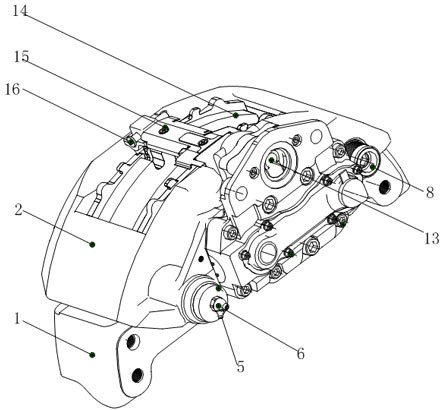
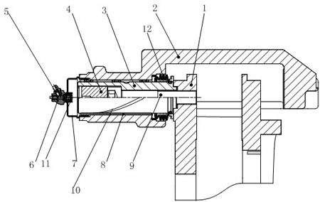
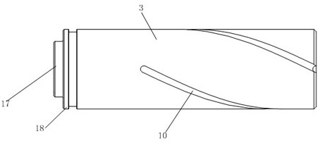
[0012] Such as Figure 1 to Figure 3 As shown, the disc brake lubrication system of the present invention includes a bracket 1, a floating inlay 2, a guide pin 3, a block 4, a grease nipple 5, a grease joint 6, a steel cap 7, a bushing 8, a bolt 9, and a spiral groove 10, The floating inlay 2 is located on the top of the bracket 1, the guide pin 3 is located on the side of the bracket 1, the block 4 is located in the guide pin 3, the steel cap 7 is located on one side of the floating inlay 2, the grease joint 6 is connected to the steel cap 7, The oil nozzle 5 communicates with the grease joint 6, the bushing 8 is located between the bracket 1 and the guide pin 3, the bracket 1 and the block 4 are connected by bolts 9, and the spiral groove 10 is located on the outside of the guide pin 3...


PUM


Abstract

The invention discloses a disc brake lubricating system and a manufacturing method thereof. The disc brake lubricating system comprises a support and the like. A floating inlay is located on the support, a guide pin is located on the side face of the support, a check block is located in the guide pin, a steel cap is located at one side of the floating inlay, a lubricating grease connector is connected with the steel cap, an oil nozzle is communicated with the lubricating grease connector, the bush is located between the support and the guide pin, and the support is connected with the check block through bolts. A spiral groove is formed at the outer side of the guide pin. A first spring is arranged at one end of the lubricating grease connector, and a second spring is arranged on the outerside of the guide pin; and a protrusion and a top cover are arranged at one side of the guide pin, and the protrusion is fixed to one side of the top cover. A lubricating grease supplementing channelis added, meanwhile, the effective storage space of lubricating grease is enlarged, and the braking safety is improved.

Description

technical field [0001] The invention relates to a lubricating system and a manufacturing method thereof, in particular to a disc brake lubricating system and a manufacturing method thereof. Background technique [0002] In the field of commercial vehicle braking systems, drum brakes were widely used at the earliest. Drum brakes are not only durable, but also have a large braking force. However, drum brakes have slow braking response and are too closed in structure, resulting in poor heat dissipation. After being heated, the diameter increases, which increases the stroke of the brake and reduces the braking effect; the disc brake makes up for the shortcomings of the drum brake. The hollow design of the brake disc has quick response, good heat dissipation and drainage, and can be used as a The high-frequency braking action meets the requirements of the ABS system, so there is a tendency for disc brakes to completely replace drum brakes; however, disc brakes also have shortcomi...

Claims


Application Information

Patent Timeline
Patent Type & Authority Applications(China)
IPC IPC(8): F16D65/095F16N1/00B23P23/04
CPCB23P23/04F16D65/0087F16D65/095F16N1/00
Inventor 李凤辉
Owner 苏州多普工业技术有限公司
Learn More