Turbine pump sealing mechanism and turbine pump

A technology of sealing mechanism and turbo pump, which is applied in the direction of pumps, pump components, mechanical equipment, etc., can solve the problems of large loss and low sealing reliability, and achieve the effects of reducing the acting pressure, ensuring the sealing performance and reducing the wear of the seal

Active Publication Date: 2020-12-01
BEIJING XINGJI RONGYAO SPACE TECH CO LTD +2
View PDF9 Cites 1 Cited by
  • Summary
  • Abstract
  • Description
  • Claims
  • Application Information

AI Technical Summary

Problems solved by technology

[0005] In order to solve the problems of low sealing reliability of existing turbo pumps and large losses in high-pressure environments, the present invention provides a turbo pump sealing mechanism suitable for high-speed, high-pressure and easy-to-vaporize media and a turbo pump using the mechanism

Method used


Image

  • Turbine pump sealing mechanism and turbine pump
  • Turbine pump sealing mechanism and turbine pump
  • Turbine pump sealing mechanism and turbine pump

Examples


Embodiment 1

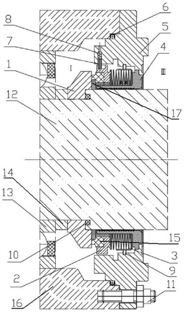
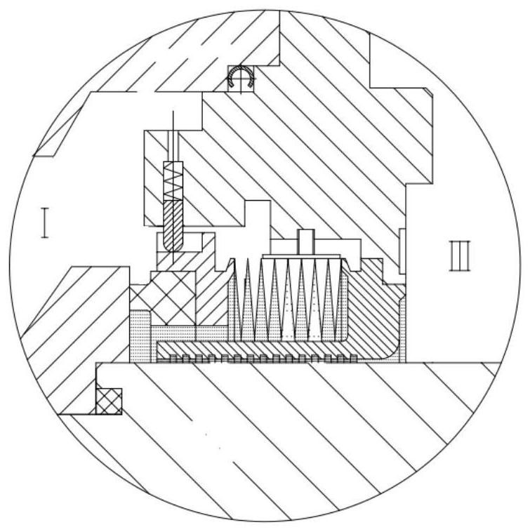
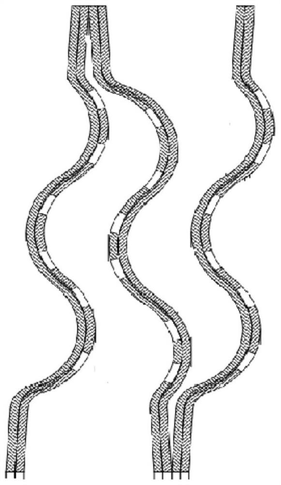
[0054] The invention provides a turbo pump sealing mechanism, see figure 1 and figure 2 . figure 1 It is a side sectional view of the turbo pump sealing mechanism of this embodiment. figure 2 for figure 1 A partially enlarged schematic diagram. image 3 It is a schematic cross-sectional view of the double-layer bellows in the sealing mechanism of the turbo pump in this embodiment. Figure 4 A schematic diagram of the end face of the double-layer bellows of the turbo pump sealing mechanism of the embodiment. Such as figure 1 and figure 2 As shown, the sealing mechanism of the turbo pump in this embodiment includes: a moving ring 1 , a stationary ring 2 , a double-layer bellows 3 , an isolation ring 4 , a sealing casing 5 and a rotating shaft 12 .

[0055] in,

[0056] The sealing housing 5 is adapted to be connected to a turbo pump housing 16 of a turbo pump.

[0057] The isolation ring 4 is sheathed on the rotating shaft 12 and forms a seal on a contact surface wit...

Embodiment 2

[0072] The present invention also provides a turbo pump, wherein the turbo pump sealing mechanism as described in Embodiment 1 is arranged between the turbo pump assembly and the pump assembly.

[0073] in,

[0074] The rotating shaft 12 is connected to the turbine assembly.

[0075] The moving ring 1, the static ring 2 and the double-layer bellows 3 are arranged on the side close to the pump assembly.

[0076] The sealed housing 5 passes through a connecting piece, such as figure 1 The screw 11 in the middle is connected and fastened with the turbo pump casing 16.

[0077] The connection relationship of various components inside the turbo pump sealing mechanism is as described in the first embodiment above, and will not be repeated here.

[0078] The turbo pump sealing mechanism provided in this embodiment, by using the above turbo pump sealing mechanism, has high sealing reliability and low loss in a high-pressure environment, and is suitable for use in a high-speed, high...


PUM


Abstract

The invention discloses a turbine pump sealing mechanism and a turbine pump applying the same. The turbine pump sealing mechanism comprises a moving ring, a static ring, a double-layer corrugated pipe, an isolating ring, a sealing shell and a rotating shaft; the sealing shell is suitable for being connected with a turbine pump shell of the turbine pump; the isolating ring is arranged on the rotating shaft in a sleeving mode and forms a seal with the contact surface of the rotating shaft; the end face of an outer ring of the isolating ring abuts against the inner wall of the sealing shell to form a seal, the moving ring is arranged on the end surface of one side of the rotating shaft in a sleeving mode and attached to the end surface of one side of the static ring to form a seal; the staticring is welded to the isolating ring in a sleeving mode, and the end face of one side of the static ring is attached to the moving ring to form a seal; the end face of the other side of the static ring is connected with the end face of one side of the isolating ring through the double-layer corrugated pipe; the two ends of the double-layer corrugated pipe are connected with the static ring and the isolating ring correspondingly; and small holes are uniformly formed in the side, in contact with leaked media, of the double-layer corrugated pipe. The turbine pump sealing mechanism is high in sealing reliability, small in loss in a high-pressure environment and suitable for being used in a high-speed and high-pressure medium environment easy to vaporize.

Description

technical field [0001] The invention relates to the technical field of sealing, in particular to a turbo pump sealing mechanism and a turbo pump using the sealing mechanism. Background technique [0002] As an important part of the liquid oxygen methane engine, the methane pump is used to deliver the low-temperature methane required for the engine to work. The methane pump is next to the turbine. Usually, a sealing device is set between the methane pump and the turbine in the turbo pump of the liquid rocket engine, so as to avoid a large amount of meeting between the two mediums of low-temperature methane and high-temperature gas. At present, there are mainly two types of seals used between the turbine and the cryopump at home and abroad: [0003] 1) Non-contact seal, the principle is to use the partial gap of the labyrinth to realize step-by-step decompression and sealing, such as floating ring, labyrinth seal, etc. This kind of seal has a simple structure, but the sealing...

Claims


Application Information

Patent Timeline
Patent Type & Authority Applications(China)
IPC IPC(8): F04D29/12F04D29/10F04D29/043F04D29/046F04D29/60
CPCF04D29/126F04D29/106F04D29/043F04D29/046F04D29/605
Inventor 彭小波魏一张玺李建克
Owner BEIJING XINGJI RONGYAO SPACE TECH CO LTD
Why Eureka
Try Eureka