
Grid plate and braided rope combined sealing structure

A sealing structure and grille technology, which is applied in the direction of leakage prevention, engine components, machines/engines, etc., and can solve problems affecting sealing performance and increasing leakage

Active Publication Date: 2020-12-01
TSINGHUA UNIV
View PDF9 Cites 1 Cited by
  • Summary
  • Abstract
  • Description
  • Claims
  • Application Information

AI Technical Summary

Problems solved by technology

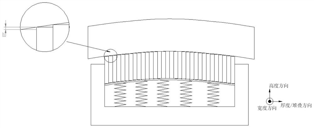
[0008] Because the grid seal is composed of multiple small grid plates, after thermal deformation of the side wall, pores will appear between the grid plate and the deformed side wall, which will increase the leakage and affect the performance of the seal

Method used


Image

  • Grid plate and braided rope combined sealing structure
  • Grid plate and braided rope combined sealing structure
  • Grid plate and braided rope combined sealing structure

Examples


Embodiment Construction

[0027] The present invention is described in further detail below in conjunction with embodiment.

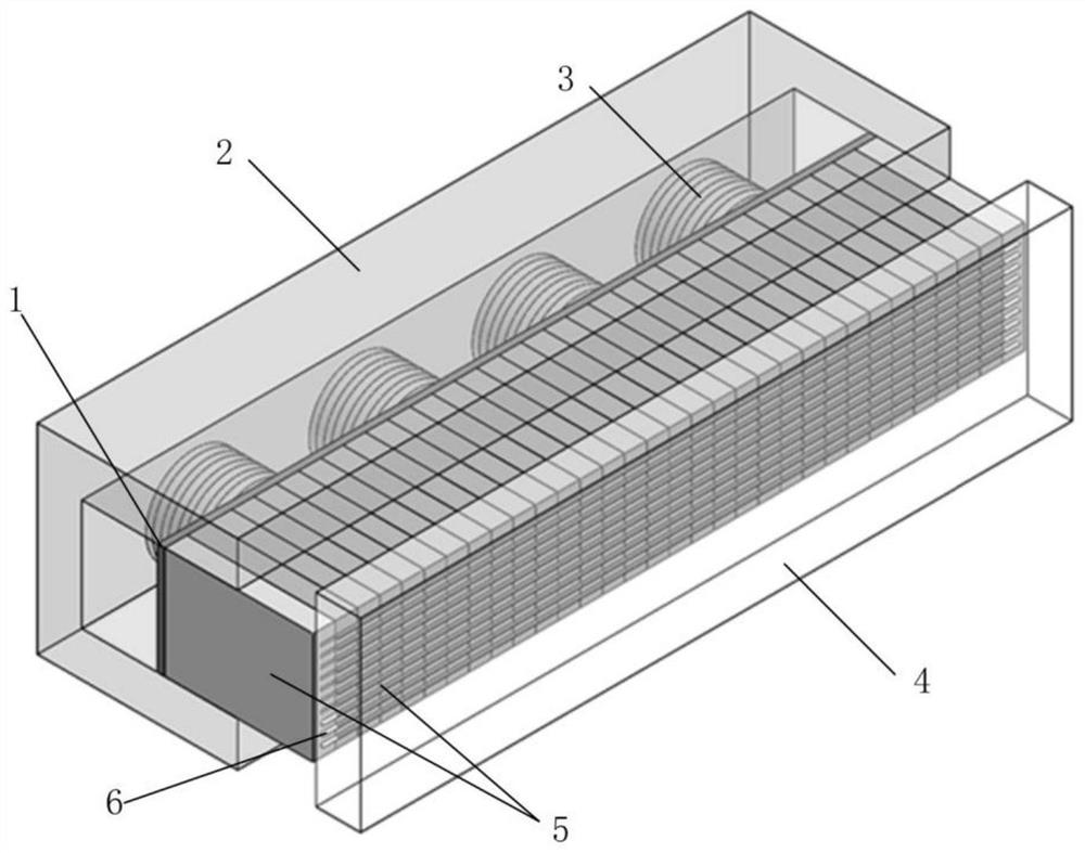
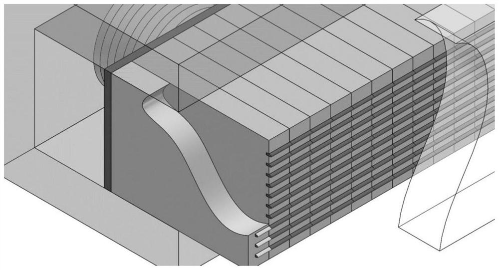
[0028] Such as Figure 1-Figure 4 As shown: the sealing structure is mainly for reducing the gap between the side wall 4 and the grid plate group 5 after thermal deformation. After thermal deformation, the side wall 4 is concave relative to the grid plate set 5 , and an approximately triangular gap is formed between the grid plate set 5 and the side wall 4 . In order to fill the gap, micron-scale grooves are processed at one end of the grid plate group 5 in contact with the side wall 4, and the length of the grooves of the grid plate group 5 at both ends should be less than the thickness of the grid plate group 5, so as to avoid the fiber braided rope 6 from the side wall 4. drop.

[0029] After processing the grooves, micron-scale fiber braided ropes 6 are placed in the grooves in sections (ideally, each groove of each grid plate), and the segmented placement is conducive to ...


PUM

PropertyMeasurementUnit
Groove widthaaaaaaaaaa
Depthaaaaaaaaaa

Abstract

A grid plate and braided rope combined sealing structure comprises a grid plate set making contact with the side wall, wherein a micron-sized groove is machined in the end, making contact with the side wall, of the grid plate set, and the groove is used for containing micron-sized fiber braided ropes. The section size of the fiber braided ropes is larger than the depth of the groove, an elastic thin plate is arranged at the other end of the grid plate set, an elastic element used for providing pre-tightening pressure is arranged on the elastic thin plate, and the elastic element is arranged ona grid plate base sleeve. According to the invention, the gap between the grid plate set and the thermally deformed side wall is blocked by utilizing the elastic deformation of the fiber braided ropes, so that the sealing leakage amount is reduced; the fiber braided ropes can also compensate gaps caused by deformation retardation of the elastic thin plates.

Description

technical field [0001] The invention relates to the technical field of dynamic sealing under high-temperature working conditions such as aero-engines and steam turbines, and in particular to a sealing structure composed of grid plates and braided ropes. Background technique [0002] The high-temperature dynamic sealing structure is one of the key technologies of the control surface of hypersonic aircraft, and plays an important role in the safe operation of the aircraft. The current high-temperature dynamic sealing technologies mainly include: packing seal, labyrinth seal, dry gas seal, brush seal, fingertip seal and grid seal, etc. Packing seals are mainly used in rotary seals, and the sealing performance of packing is greatly affected by temperature, so it is only suitable for working conditions where the temperature is less than 250°C. The labyrinth seal is a non-contact dynamic seal, which uses the throttling effect of the fluid in the gap to limit leakage, and the leak...

Claims


Application Information

Patent Timeline
IPC IPC(8): F01D11/00F01D25/00
CPCF01D11/003F01D25/005
Inventor 李永健祁志浩黄伟峰刘莹郭飞刘向锋贾晓红赵炬颖李鸿举李国志
Owner TSINGHUA UNIV
Learn More