Material clamping fixture

A clamping clip and left clamping technology, applied in the field of clamping fixtures, can solve the problems of poor welding quality, inconvenient welding, affecting the credibility of enterprises, etc., and achieve increased welding surface, convenient welding, and enlarged welding surface. Effect

Inactive Publication Date: 2020-12-01
永州瑞麟电业有限公司
View PDF0 Cites 0 Cited by
  • Summary
  • Abstract
  • Description
  • Claims
  • Application Information

AI Technical Summary

Problems solved by technology

[0002] It turns out that the power connector is polished with a grinding wheel. When grinding the grinding wheel, a person holds the fixture to clamp the power connector for grinding, first polishes the positive side of the power connector, and then polishes the negative side of the power connector. When grinding, hand shaking will have a certain impact on the polished welding surface of the power connector. For example, the polished welding surface is sometimes wide and sometimes narrow, and the position of the polished welding surface is sometimes high and sometimes low. It is inconvenient to weld, and some of them have poor welding quality due to the narrow welding surface, and the qualified rate of welded power connector products is not high, which not only affects the credibility of the enterprise, but also has a certain impact on the economic benefits of the enterprise

Method used


Image

  • Material clamping fixture

Examples


Embodiment Construction

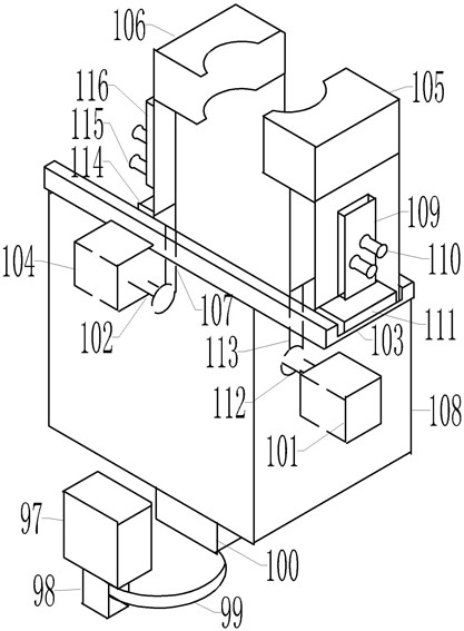
[0013] Referring to accompanying drawing: 1, a kind of clamping clamp comprises motor 97, left driving cylinder 104, right driving cylinder 101, support 108, and the driving shaft 98 of motor 97 is connected with driven shaft 100 through belt 99, and left driving cylinder 104 is provided with Left telescopic rod 102, this left telescopic rod 102 is connected with left clamping claw 106 through left connecting rod 107; connect. Both the left clamping claw 106 and the right clamping claw 105 are installed in the track groove 103 . The track groove 103 is "()" shape, and the left clamping claw and the right clamping claw are convenient to run back and forth in the track groove.

[0014] A left sliding plate 114 is provided at the lower end of the left clamping claw 106 , and a right sliding plate 111 is provided at the lower end of the right clamping claw 105 . The left and right sliding plates can make the left and right clamping claws slide back and forth easily.

[0015] A ...


PUM


Abstract

The invention discloses a material clamping fixture. The fixture comprises a motor (97), a left driving air cylinder (104), a right driving air cylinder (101) and a support (108), a driving shaft (98)of the motor (97) is connected with a driven shaft (100) through a belt (99), the left driving air cylinder (104) is provided with a left telescopic rod (102), and the left telescopic rod (102) is connected with a left clamping jaw (106) through a left connecting rod (107); the right driving air cylinder (101) is provided with a right telescopic rod (112), and the right telescopic rod (112) is connected with the right clamping jaw (105) through a right connecting rod (113). During polishing, the clamping fixture can enlarge the polished welding surface of the power connector.

Description

technical field [0001] The invention relates to a clamp for clamping materials, in particular to a clamp for clamping a power connector. Background technique [0002] It turns out that the power connector is polished with a grinding wheel. When grinding the grinding wheel, a person holds the fixture to clamp the power connector for grinding, first polishes the positive side of the power connector, and then polishes the negative side of the power connector. When grinding, hand shaking will have a certain impact on the polished welding surface of the power connector. For example, the polished welding surface is sometimes wide and sometimes narrow, and the position of the polished welding surface is sometimes high and sometimes low. It is inconvenient to weld, some of them have poor welding quality because the welding surface is too narrow, and the qualification rate of welded power connector products is not high, which not only affects the credibility of the enterprise, but al...

Claims


Application Information

Patent Timeline
Patent Type & Authority Applications(China)
IPC IPC(8): B24B41/06
CPCB24B41/06
Inventor 张湘屏
Owner 永州瑞麟电业有限公司
Why Eureka
Try Eureka