Combined valve bank for compressed air treatment of armored car
A technology of compressed air and combined valve, applied in the direction of fluid pressure actuating system components, servo motor components, fluid pressure actuating devices, etc., can solve the problem of air leakage that cannot be ignored, affects system reliability, and occupies a large space for pipelines and other problems, to achieve the effect of reducing assembly cost, improving convenience and simple structure
- Summary
- Abstract
- Description
- Claims
- Application Information
AI Technical Summary
Problems solved by technology
Method used
Image
Examples
Embodiment 1
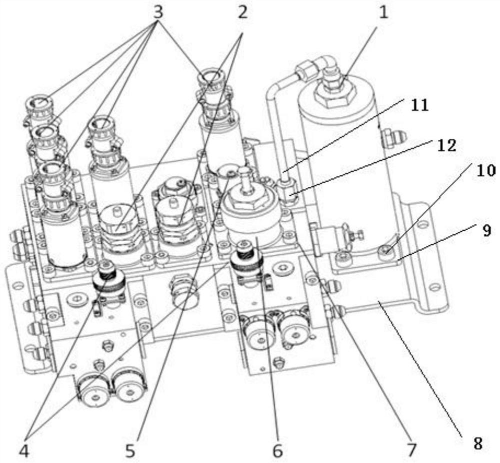
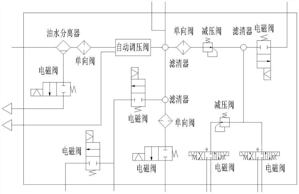
[0029] Such as figure 1 and figure 2 As shown, the present invention is a combined valve group for compressed air treatment for armored vehicles, including a gas treatment system located between the gas source device and the actuator, the gas treatment system includes an oil-water separator 1 and a plurality of control components, It also includes a valve seat 7, on which an air source interface, a load interface, and an airflow channel located inside it are arranged, and the oil-water separator 1 and the control elements are installed on the valve seat 7, and the respective internal air channels Both are connected with the air flow channel, and the air source device sends the gas to the air flow channel inside the valve seat 7 through the air source interface, and then sends the gas to the actuator from the load interface after passing through the gas treatment system.
[0030] The air source device is a compressed air generating device, and is also equipped with auxiliary ...
Embodiment 2
[0034] This embodiment is an illustration of the installation structure of the oil-water separator 1 .
[0035] Such as figure 2 As shown, in the present invention, the oil-water separator 1 is fixed on one side of the valve seat 7 through a connection assembly, and the connection assembly includes a bottom plate 8, a mounting plate 9 and screws 10, and one side of the bottom plate 8 is connected to the valve seat 7, the mounting plate 9 is fixed on the bottom of the oil-water separator 1, and a plurality of light holes are arranged around it, the number of the screws 10 is consistent with the number of light holes, and the ends of the rods respectively pass through After a light hole, it is threadedly connected with base plate 8.
Embodiment 3
[0037]This embodiment is based on the above-mentioned embodiments, and describes the sealing connection between the air outlet port of the oil-water separator and the valve seat 7 .
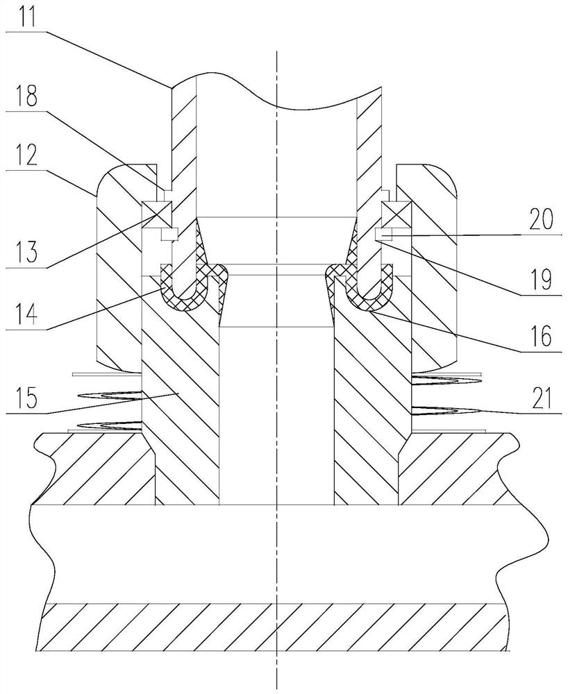
[0038] Such as image 3 As shown, in the present invention, the air outlet end of the air outlet pipeline 11 of the oil-water separator 1 is sealed and connected to the air inlet end communicating with it on the air flow channel through a connecting assembly, and the connecting assembly includes nuts 12 whose axes coincide with each other, bearings 13. The sealing ring 14 and the externally threaded cylinder 15. The bearing 13 is sleeved on the air outlet pipe 11 and axially fixed on the air outlet pipe 11. The nut 12 is sleeved on the bearing 13, and it is connected to the outer surface of the bearing 13. Ring interference fit, the bottom of the external thread cylinder 15 is inserted into the valve seat 7, and is sealed and welded with the valve seat 7, and its top is inserted into the inner ho...
PUM
 Abstract
Description
Claims
Application Information
 - R&D
- Intellectual Property
- Life Sciences
- Materials
- Tech Scout
- Unparalleled Data Quality
- Higher Quality Content
- 60% Fewer Hallucinations
Browse by: Latest US Patents, China's latest patents, Technical Efficacy Thesaurus, Application Domain, Technology Topic, Popular Technical Reports.
© 2025 PatSnap. All rights reserved.Legal|Privacy policy|Modern Slavery Act Transparency Statement|Sitemap|About US| Contact US: help@patsnap.com


