Fan fan-blade positioning structure

A positioning structure and fan blade technology, which is applied to components of pumping devices for elastic fluids, non-variable pumps, machines/engines, etc., can solve the problem of reducing the service life and quality of fans, affecting bearings and fan shafts Core life, occupied structure space and other issues, to achieve the effect of improving the strength of the shaft core and fan quality, improving the rotation stability, and reducing the overall height

Pending Publication Date: 2020-11-27
太仓欣华盈电子有限公司
View PDF0 Cites 0 Cited by
  • Summary
  • Abstract
  • Description
  • Claims
  • Application Information

AI Technical Summary

Problems solved by technology

[0003] like figure 1 As shown, the upper buckle-type positioning structure is as follows: a buckle ring is arranged on the inner side of the upper end of the middle tube, and the buckle ring 13 located at the upper end of the bearing is pressed by the pressure ring at the upper end of the middle tube. On the one hand, the positioning of the bearing is realized, and on the other hand, the buckle ring is stuck The annular groove on the outer wall of the fan blade shaft core realizes the axial stop positioning of the fan blade shaft core. This structure occupies the space of the structure, which leads to the shortening of the bearing length, affects the bearing area of ​​the shaft, and affects the bearing and the fan blade shaft. The life of the core reduces the quality of the fan. In addition, when the shaft core is inserted into the bearing, if there is no guide, it is easy to be crushed during the pressing process;
[0004] like figure 2 As shown, the lower retaining ring positioning structure is as follows: a lower retaining ring is arranged between the lower end of the bearing and the step of the middle tube, and the lower retaining ring clamps the annular groove at the lower end of the outer wall of the fan blade shaft core to realize the positioning of the fan blade shaft core. Axial stop positioning, which takes up a lot of space in the structure, the bearing will be very short, and the shaft receiving area is small, which will affect the life and quality of the fan. The bearing and shaft core of the cooling fan are in the
[0005] It can be seen that the existing two fan center structures will occupy the space of the bearing structure, resulting in the shortening of the bearing, reducing the service life and quality of the fan. In addition, there will be an extra buckle part, resulting in cumbersome assembly and high cost of the fan.

Method used


Image

  • Fan fan-blade positioning structure
  • Fan fan-blade positioning structure
  • Fan fan-blade positioning structure

Examples


Embodiment

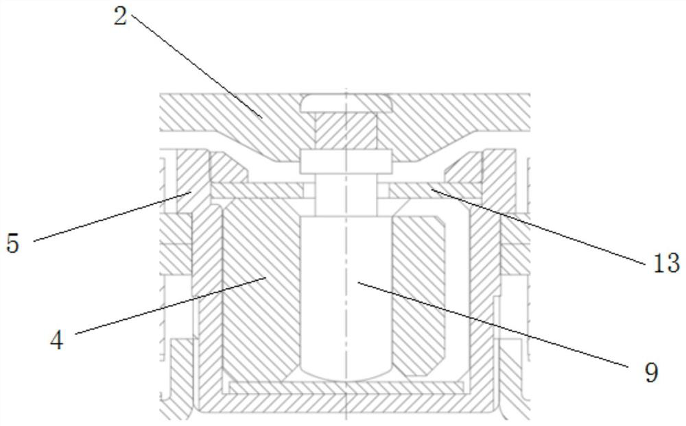
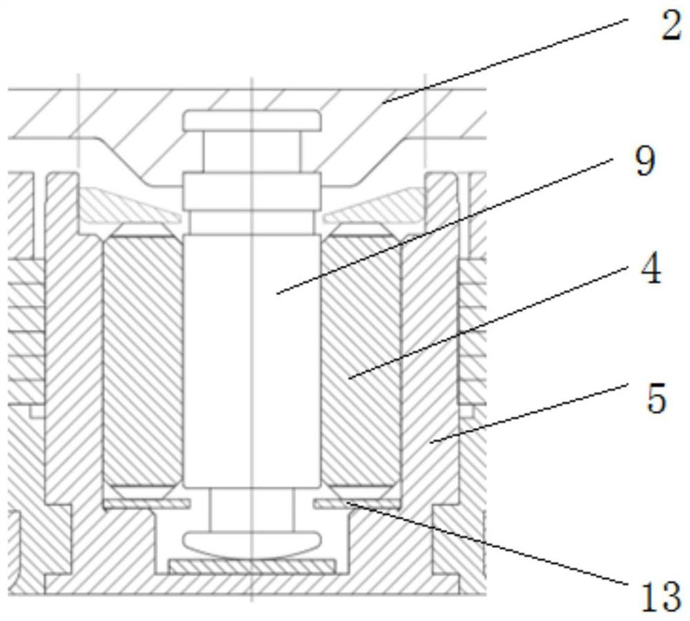
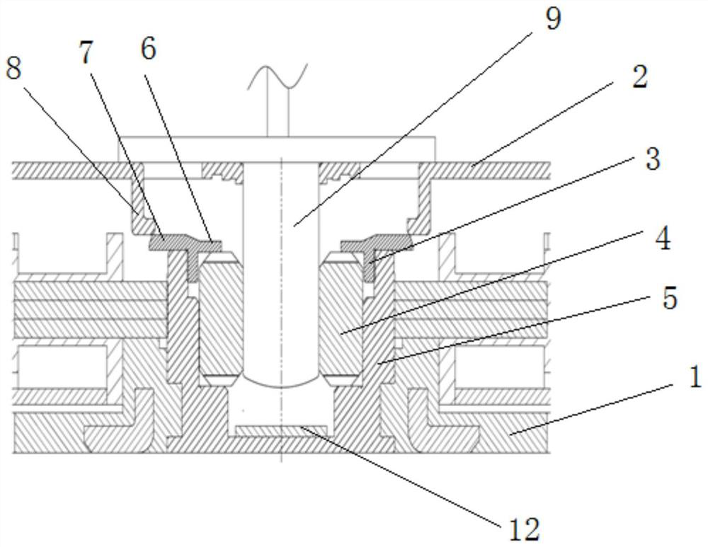
[0025] Example: Please refer to image 3 , 4 As shown, a fan blade positioning structure includes a fan housing 1, a fan blade 2, a positioning ring 3, a bearing 4 and a middle tube 5, the middle tube 5 is fixedly installed in the fan housing 1, and the bearing 4 is inserted In the middle tube 5, the positioning ring 3 is fixedly installed on the middle tube 5, and the positioning ring 3 is axially stopped with a limit stop wall 6 and a first buckle 7, and the limit stop wall 6 extends radially. Into the inner side of the middle tube 5 and stop on the upper end surface of the bearing 4, the second buckle 8 is fixed on the motor housing of the fan blade 2, and the second buckle 8 and the first buckle 7 can axially stop And the fastening connection of relative rotation in the circumferential direction. In this structure, the first buckle 7 is designed on the positioning ring 3, and the second buckle 8 is designed on the motor housing of the fan blade 2. Through the first buckl...


PUM


Abstract

The invention discloses a fan fan-blade positioning structure. The fan fan-blade positioning structure comprises a fan shell, fan blades, positioning rings, bearings and a middle pipe. The middle pipeis fixedly mounted in the fan shell, the bearings are inserted into the middle pipe, the positioning rings are fixedly mounted on the middle pipe, limiting blocking walls and first buckles are arranged on the positioning rings in an axial locking manner, the limiting blocking walls stretch into the inner side of the middle pipe in the radial direction and are blocked on the upper end faces of thebearings, second buckles are fixedly arranged on motor shells of the fan blades, and the second buckles and the first buckles can be in buckled connection in an axial locking manner by relatively rotating in the circumferential direction. The internal space of the middle pipe is greatly saved, the lengths and the areas of the bearings can be effectively increased under the condition that the height of a fan is unchanged, meanwhile, a shaft core is prevented from being grooved, the strength of the shaft core and the quality of the fan are improved, the service life of the fan is prolonged, andthe rotating stability of the fan blades is improved.

Description

technical field [0001] The invention relates to a cooling fan, in particular to a fan blade positioning structure. Background technique [0002] At present, the traditional fan center structure adopts the grid buckle type or the lower buckle type positioning, of which: [0003] like figure 1 As shown, the upper buckle-type positioning structure is as follows: a buckle ring is arranged on the inner side of the upper end of the middle tube, and the buckle ring 13 located at the upper end of the bearing is pressed by the pressure ring at the upper end of the middle tube. On the one hand, the positioning of the bearing is realized, and on the other hand, the buckle ring is stuck The annular groove on the outer wall of the fan blade shaft core realizes the axial stop positioning of the fan blade shaft core. This structure occupies the space of the structure, which leads to the shortening of the bearing length, affects the bearing area of ​​the shaft, and affects the bearing and ...

Claims


Application Information

Patent Timeline
Patent Type & Authority Applications(China)
IPC IPC(8): F04D29/34
CPCF04D29/34
Inventor 张国良王宏飞朱坤
Owner 太仓欣华盈电子有限公司
Why Eureka
Try Eureka