


Quick Research
Generate reliable direction feasibility study reports for your R&D in just a few steps.

Technical Q&A
Discover and master advanced knowledge NOW. Basics, ideas, possibilities, all at once.

Find Solutions
As an expert in R&D theories, this can generate solutions to your technical problems instantly.

Evaluate Feasibility
Analyze your overall solution with one click, know your potential R&D risks in advance.

Monitor Landscape
Get weekly tech updates, stay abreast of the latest tech innovations and key insights.
Curtain fabric cutting device for textile process
A cutting device, a technology for curtain fabrics, applied in textiles and papermaking, cutting of textile materials, etc., can solve the problems of affecting splicing, labor consumption, inconsistent length, etc., and achieve the effect of simple operation, consistent distance, and consistent length
- Summary
- Abstract
- Description
- Claims
- Application Information
AI Technical Summary
Problems solved by technology
Method used
Image

Examples
Embodiment 1
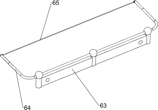
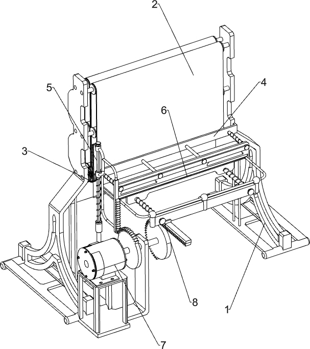
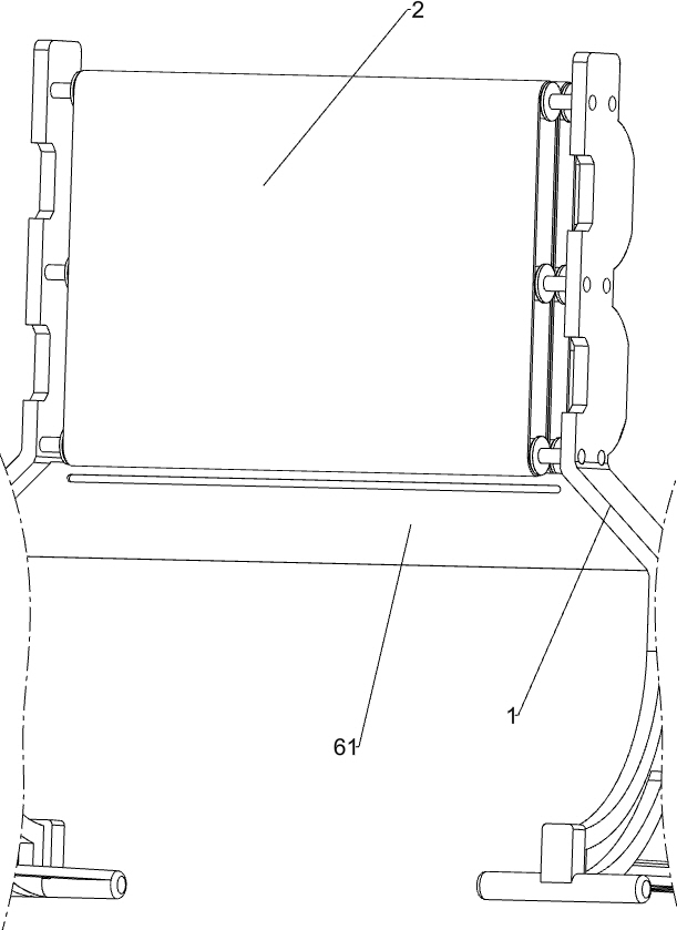
[0025] A curtain cloth cutting device for textile technology, such as Figure 1-4 As shown, it includes a support 1, a conveyor belt 2, a transmission gear 3 and a guide rail 4, and a conveyor belt 2 is rotatably connected between the front and rear sides of the bracket 1 on the left and right sides, and the gap between the two conveyor belts 2 is just enough To accommodate the curtain cloth, transmission gears 3 are connected to the transmission shafts below the two conveyor belts 2, and the two transmission gears 3 are meshed with each other. A guide rail 4 is connected between the front sides of the brackets 1 on both sides, and a moving assembly 5 and Cutting assembly 6 , a moving assembly 5 is provided between the support 1 and the conveyor belt 2 , and a cutting assembly 6 is provided between the guide rail 4 and the support 1 .
[0026] The moving assembly 5 includes a guide rod 51, a sliding frame 52, a drive rack 53, a one-way gear 54 and a compression spring 55. The ...
Embodiment 2
[0030] On the basis of Example 1, such as Figure 5 As shown, a drive assembly 7 is also included, and the drive assembly 7 includes a mounting frame 71, a servo motor 72, a rotating shaft 73, a first sector gear 74, a connecting frame 75 and a spur rack 76, and the front side of the left side bracket 1 is connected with a mounting Frame 71, servomotor 72 is installed on the top of mounting frame 71, is connected with rotating shaft 73 on the output shaft of servomotor 72, is connected with connecting frame 75 on the front side of sliding frame 52, is connected with spur rack 76 on the connecting frame 75, and rotating shaft 73 left The first sector gear 74 is connected to the upper part, and the first sector gear 74 will mesh with the spur rack 76 .
[0031] When it is necessary to pull the sliding frame 52 to move downward, the servo motor 72 can be started to drive the rotating shaft 73 to rotate, and the rotating shaft 73 rotates to drive the first sector gear 74 to rotate...
PUM
 Abstract
Description
Claims
Application Information
 - R&D Engineer
- R&D Manager
- IP Professional
- Industry Leading Data Capabilities
- Powerful AI technology
- Patent DNA Extraction
Browse by: Latest US Patents, China's latest patents, Technical Efficacy Thesaurus, Application Domain, Technology Topic, Popular Technical Reports.
© 2024 PatSnap. All rights reserved.Legal|Privacy policy|Modern Slavery Act Transparency Statement|Sitemap|About US| Contact US: help@patsnap.com