
Underwater component detection equipment for roads and bridges in civil engineering and using method thereof

A detection equipment and civil engineering technology, applied in underwater operation equipment, bridge parts, bridge construction, etc., can solve problems such as difficulty in ensuring the integrity and accuracy of data collection, difficulty in adjusting the angle of detection equipment, and omission of detection equipment data. Achieve the effect of ensuring integrity and accuracy, avoiding manual launching, and improving detection safety

Active Publication Date: 2020-11-27
覃晓军
View PDF8 Cites 3 Cited by
  • Summary
  • Abstract
  • Description
  • Claims
  • Application Information

AI Technical Summary

Problems solved by technology

[0006] The object of the present invention is to provide an underwater component detection device for road bridges in civil engineering and its use method, which has the advantages of high detection safety, flexible adjustment of detection angle, and the integrity and accuracy of detection data. It solves the problem that the staff dive into the water with the detection equipment and dive to the detection position. During this period, due to the increase of the diving depth, the water pressure gradually increases, causing pressure on the staff, and even causing injury to the staff, and the safety is low. , the user holds the detection device to collect data, it is difficult for the user to adjust the posture underwater, and the angle of the detection device is also difficult to adjust, resulting in omissions in the data collected by the detection device, and it is difficult to ensure the integrity and accuracy of data collection.

Method used


Image

  • Underwater component detection equipment for roads and bridges in civil engineering and using method thereof
  • Underwater component detection equipment for roads and bridges in civil engineering and using method thereof
  • Underwater component detection equipment for roads and bridges in civil engineering and using method thereof

Examples


Embodiment Construction

[0030] The following will clearly and completely describe the technical solutions in the embodiments of the present invention with reference to the accompanying drawings in the embodiments of the present invention. Obviously, the described embodiments are only some, not all, embodiments of the present invention. Based on the embodiments of the present invention, all other embodiments obtained by persons of ordinary skill in the art without making creative efforts belong to the protection scope of the present invention.

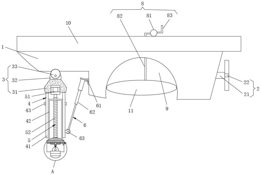
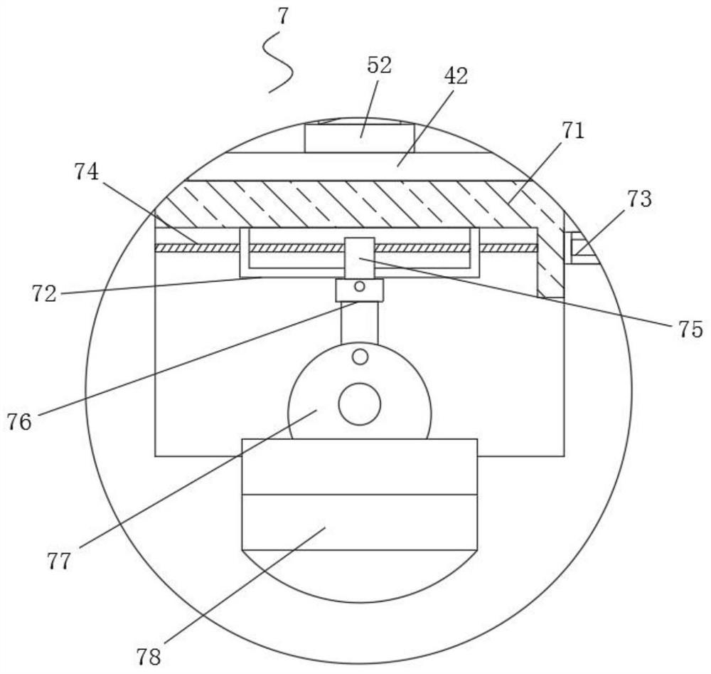
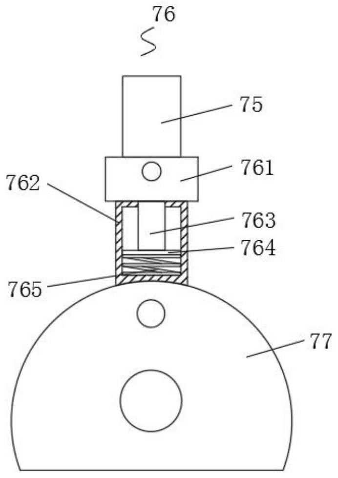
[0031] see Figure 1-5, the present invention provides a technical solution, a kind of underwater component detection equipment for road bridges in civil engineering, comprising a submerged hull 1, a driving mechanism-2 is arranged on the right side of the submerged hull 1, and the bottom of the submerged hull 1 The left side of the swing mechanism 3 is provided with a swing mechanism 3, and the bottom of the swing mechanism 3 is provided with a limit mechanis...


PUM


Abstract

The invention discloses underwater component detection equipment for roads and bridges in civil engineering and a using method thereof. A diving ship body is included. A driving mechanism I is arranged on a right side of the diving ship body; and a swing mechanism is arranged on the left side of the bottom of the diving ship body, a limiting mechanism is arranged at the bottom of the swing mechanism, an extension mechanism is arranged in the limiting mechanism, a driving mechanism II is arranged on one side of the bottom of the diving ship body, and an adjusting mechanism is arranged at the bottom of the limiting mechanism. In the invention, when the bridge is detected, the detection equipment is installed through using the equipment, manual handheld detection equipment is replaced, manuallaunching is avoided, a user is prevented from being hurt underwater, and detection safety is improved; and then, a detection angle can be flexibly adjusted when the detection equipment is underwater, the detection angle can also be adjusted through the driving mechanism I, and therefore comprehensiveness and accuracy of detection data are guaranteed.

Description

technical field [0001] The invention relates to the technical field of road bridge detection, in particular to an underwater component detection device for road bridges in civil engineering and a method for using the same. Background technique [0002] Due to the scattered locations of bridges, different technical standards used in construction, and differences in bridge structure forms, there are great differences in the operating conditions of bridges in the road network. According to the inspection results of some bridges in recent years, some bridges have different degrees of disease. The main manifestations are: irregular cracks in the structure, concrete spalling and exposed reinforcement, water erosion of the beam body and the pier cap beam, etc. These factors have seriously affected the safety and durability of the bridge. [0003] In the detection of roads and bridges, the detection of bridges will be more cumbersome, because it is divided into two parts, one is loc...

Claims


Application Information

Patent Timeline
Patent Type & Authority Applications(China)
IPC IPC(8): B63G8/00B63G8/08B63G8/14E01D19/10
CPCB63G8/001B63G8/08B63G8/14E01D19/106
Inventor 覃晓军
Owner 覃晓军
Learn More