Eureka AIR delivers breakthrough ideas for toughest innovation challenges, trusted by R&D personnel around the world.

A motor with fast heat dissipation function of stator

A stator and fast technology, applied in the direction of electric components, electromechanical devices, electrical components, etc., can solve the problems of heating of the stator and rotor, the influence of the stator on the stability of the motor, and the reduction of temperature.

Active Publication Date: 2021-07-06
大洋智能(江苏)科技产业有限公司
View PDF5 Cites 0 Cited by
  • Summary
  • Abstract
  • Description
  • Claims
  • Application Information

AI Technical Summary

Problems solved by technology

[0003] The main principle of the motor is the electromagnetic effect. After the stator is connected to the alternating current, the rotor is driven to rotate through the electromagnetic effect. However, under the electromagnetic effect, the heating of the stator is a problem that affects the stability of the motor. However, this heat dissipation method still needs to dissipate heat through a long path from the coil installation position of the stator to the surface of the casing. The temperature on the path decreases, and the temperature of the stator is much higher than that of the surface of the casing. It can only be called the motor. The heat dissipation is not the heat dissipation of the stator, how to effectively control the temperature of the stator is an urgent problem to be solved to improve the performance of the motor
[0004] In addition, when the motor is started, due to the existence of external loads, the speed can only be slowly increased. When the rotor is running at low speed, the electromagnetic effect is not efficient, and the stator and rotor are seriously heated. How to start the motor shaft quickly will reduce the heat generated when the motor starts.

Method used


Image

  • A motor with fast heat dissipation function of stator
  • A motor with fast heat dissipation function of stator
  • A motor with fast heat dissipation function of stator

Examples


Embodiment Construction

[0032] The following will clearly and completely describe the technical solutions in the embodiments of the present invention with reference to the accompanying drawings in the embodiments of the present invention. Obviously, the described embodiments are only some, not all, embodiments of the present invention. Based on the embodiments of the present invention, all other embodiments obtained by persons of ordinary skill in the art without making creative efforts belong to the protection scope of the present invention.

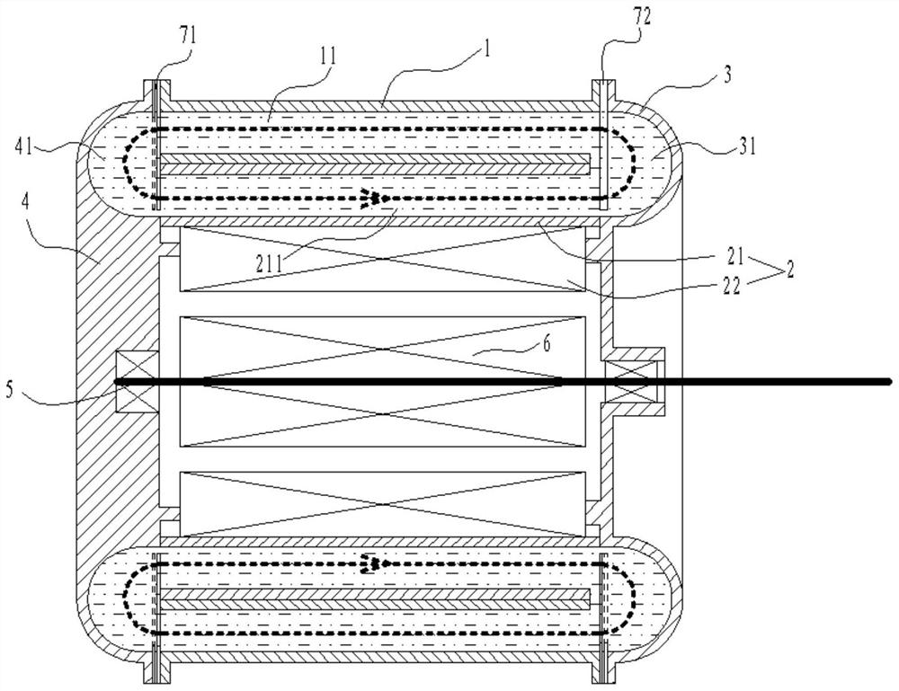
[0033] see Figure 1-8 , a motor with a stator rapid heat dissipation function, including a housing 1, a stator assembly 2, a front cover 3, a rear end cover 4, a main shaft 5 and a rotor 6, the inner wall of the housing 1 is provided with a stator assembly 2, a front cover 3, and a rear end cover 4 Connect with both ends of the shell 1 to make the shell 1 closed, the main shaft 5 is installed on the front end cover 3 and the rear end cover 4 through the doubl...


PUM


Abstract

The invention discloses a motor with a stator rapid heat dissipation function, comprising a casing, a stator assembly, a front end cover, a rear end cover, a main shaft and a rotor, a stator assembly is arranged on the inner wall of the casing, and the front end cover and the rear end cover are respectively connected to two ends of the casing The shell is closed, the main shaft is installed on the front end cover and the rear end cover through the double-end support of the bearing, the main shaft extends out of the front end cover as the output shaft of the motor, the rotor is installed on the main shaft, the rotor and the stator assembly are arranged radially face to face, and the stator assembly and the casing are arranged face to face. There is circulating cooling fluid between them. The invention quickly transfers the heat in the stator to the outer surface for heat dissipation through the magnetic fluid, and helps the stator to cool down quickly. Compared with the traditional heat dissipation structure, the thermal stability of the stator is better, and the flow of the magnetic fluid relies on electromagnetic drive. No external mechanical power is required, and the closed loop requires little maintenance.

Description

technical field [0001] The invention relates to the technical field of motors, in particular to a motor with a stator rapid heat dissipation function. Background technique [0002] The motor is a kind of machinery widely used in industry, which converts electrical energy into mechanical energy for subsequent machines. [0003] The main principle of the motor is the electromagnetic effect. After the stator is connected to the alternating current, the rotor is driven to rotate through the electromagnetic effect. However, under the electromagnetic effect, the heating of the stator is a problem that affects the stability of the motor. However, this heat dissipation method still needs to dissipate heat through a long path from the coil installation position of the stator to the surface of the casing. The temperature on the path decreases, and the temperature of the stator is much higher than that of the surface of the casing. It can only be called the motor. The heat dissipation...

Claims


Application Information

Patent Timeline
Patent Type & Authority Patents(China)
IPC IPC(8): H02K9/19H02K1/20H02K5/20H02K44/00H02K7/118H02K7/116
CPCH02K9/19H02K1/20H02K44/00H02K7/118H02K7/116H02K5/203
Inventor 方彭
Owner 大洋智能(江苏)科技产业有限公司
Why Eureka
Eureka Blog
Learn More