
Air filter blowback spray head, system and cleaning method

A technology of air filter and reverse blow nozzle, applied in the direction of fuel air filter, chemical instrument and method, separation method, etc., can solve the problem of increasing operating cost and maintenance cost, failure, maintenance cost and cost increase, and reducing engine Power and other problems, to achieve the effect of reducing maintenance cycle and labor intensity, reducing maintenance labor intensity, and reducing comprehensive air intake resistance

Active Publication Date: 2020-11-24
赵绍兴
View PDF14 Cites 1 Cited by
  • Summary
  • Abstract
  • Description
  • Claims
  • Application Information

AI Technical Summary

Problems solved by technology

Otherwise, there is a problem with the installation angle, which will lead to a deviation in the direction of the airflow, resulting in a decrease in the effective filtration area, a decrease in the performance of the air filter, and an increase in the intake resistance
And lead to shorter working hours, increased filter maintenance time and reduced service life
Market maintenance increases special tools and testing tools, making maintenance difficult
[0009] The inventor found that no matter which one of the above three forms of filter blowback structure is used, the failure, maintenance costs and costs will increase accordingly, and it is a waste of energy to use the original car compressed air to blow the air filter during maintenance.
Even with the automatic dust removal effect, but the integration is too poor, the automatic dust blowing effect is not good, and it will increase the later operation cost and maintenance cost, increase the air intake resistance of the original vehicle or equipment, and still have an air intake impact on key equipment such as the engine Hidden dangers, reducing the effective use of engine power

Method used


Image

  • Air filter blowback spray head, system and cleaning method
  • Air filter blowback spray head, system and cleaning method
  • Air filter blowback spray head, system and cleaning method

Examples


Embodiment 1

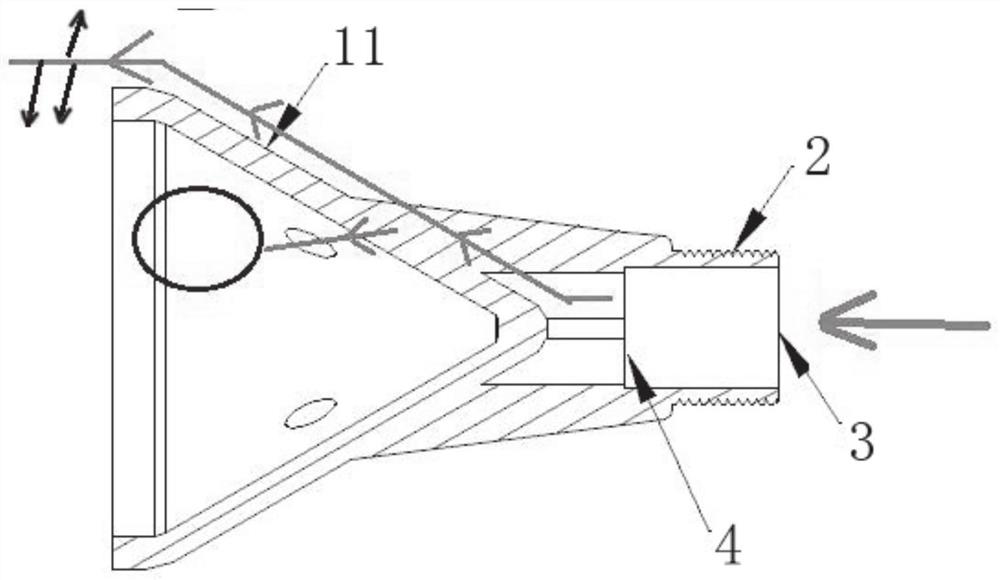
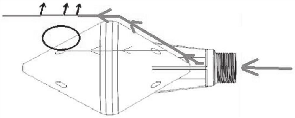
[0046] This embodiment provides an air filter blowback nozzle, such as figure 1 As shown, according to the flow direction of the reverse blowing airflow, it passes through the air inlet 3, the air outlet 4, and the conical deflector 11 in turn. The gas guiding device of the reverse blowing nozzle is composed of two conical deflectors 11 with opposite openings. The included angle formed by the flow guide shell at the cut section of the tapered flow guide along the axis may be 20 degrees to 120 degrees, preferably 65 degrees. More preferably, such as figure 1 As shown, the gas guide device is a rhombus shroud when the shaft section is rhombus.

Embodiment 2

[0048] This embodiment provides an air filter blowback nozzle system, such as Figure 8 As shown, the blowback nozzle installation device in Embodiment 1 is installed on the air filter housing connection interface 10, and the air filter housing connection interface 10 is connected to the air inlet pipe 9. The blowback gas enters the air filter through the inlet pipe 9, the connection interface 10, and the blowback nozzle 1. Under the action of the blowback nozzle 1, the gas follows the cone of the gas guide device and enters the filter element 16 in an enlarged cylindrical airflow. In the cavity, an aerodynamic turbulence is formed in the secondary air inlet chamber 15 to shake off the dust on the outer surface of the filter element 16, and a uniform air column and pressure field are formed to avoid local abnormal pressure and air flow, resulting in the 16 part of the filter element The damage of the area reduces the life of the filter element 16. Therefore, the axis of the gas...

Embodiment 3

[0051] This embodiment provides an air filter blowback nozzle system, such as Picture 9 As shown, the blowback nozzle installation device in Embodiment 1 is installed on the air filter housing connection interface 10, and the air filter housing connection interface 10 is connected to the connecting air pipe 27. The blowback gas enters the air filter through the connecting gas pipe 27, the connection interface 10, and the blowback nozzle 1. Under the action of the blowback nozzle 1, the gas enters the filter element 16 in an enlarged cylindrical airflow along the rhombus flow cover of the gas guide device. In the inner cavity of the secondary air inlet chamber 15, aerodynamic turbulence is formed in the secondary air inlet chamber 15 to shake off the dust on the outer surface of the filter element 16, and a uniform air column and pressure field are formed to avoid local abnormal pressure and air flow, which may cause the filter element The damage of the 16 part of the area redu...


PUM

PropertyMeasurementUnit
Angleaaaaaaaaaa

Abstract

The invention belongs to the technical field of automobile auxiliary components, and particularly relates to an air filter reverse blowing nozzle, a system and a cleaning method. The reverse blowing nozzle of the air filter does not comprise an air supplementing unit, a gas guiding device of the reverse blowing nozzle is composed of two conical flow guiding covers with opposite openings, and flowguiding holes are formed in the two conical flow guiding covers. The invention further provides an air filter blowback spray head system. The air filter blowback spray head system is used in the air filter blowback spray head system. The novel blowback spray head is wide in modification adaptability, is wider in adaptability than an existing automatic dust discharge additional device air filter, and is greatly reduced in comprehensive air inlet resistance compared with the existing automatic dust discharge additional air filter. An operator or a driver does not need to frequently maintain thefilter element or start the dust removal device at any time, so that the environmental pollution is reduced, the maintenance period and the labor intensity of workers on the filter element are reduced, and the service lives of core key components of related vehicles and equipment are effectively prolonged.

Description

Technical field [0001] The invention belongs to the technical field of automobile auxiliary parts, and particularly relates to an air filter blowback nozzle, a system and a cleaning method. Background technique [0002] Disclosure of the background information is only intended to increase the understanding of the overall background of the present invention, and is not necessarily regarded as an acknowledgement or in any form suggesting that the information constitutes the prior art known to those of ordinary skill in the art. [0003] The use of paper core air filters in modern automobile engines is becoming more and more common. When maintaining, only the vibration method, soft brushing method (brushing along the wrinkles) or compressed air blowback method can be used to remove the surface of the paper filter element. Dust, dirt. Even if it can be carefully maintained every time, the paper filter element cannot fully restore its original performance, and its air intake resistance...

Claims


Application Information

Patent Timeline
IPC IPC(8): F02M35/08F02M35/16
CPCF02M35/086F02M35/16B01D46/71B01D46/2403
Inventor 赵绍兴
Owner 赵绍兴
Learn More