
Textile fabric processing equipment

A technology for processing equipment and textile fabrics, applied in the field of textile fabric processing equipment, can solve the problems of low processing efficiency, affecting the actual quality of fabrics, and concentration of artificially configured mixtures, so as to improve functionality and practicability, and improve convenience and practicality performance and improve processing efficiency

Inactive Publication Date: 2020-11-24
张萍
View PDF0 Cites 2 Cited by
  • Summary
  • Abstract
  • Description
  • Claims
  • Application Information

AI Technical Summary

Problems solved by technology

[0003] The prior art has the following disadvantages: in the cloth mechanism, it is necessary to apply a certain amount of treatment agent to the cloth, or a mixture of various treatment effects, such as a mixture formed by softening agent and corresponding special glue, which can make the cloth more supple. In the prior art, the corresponding cloth processing equipment is relatively scattered, and after the cloth is processed, wrinkles and stress concentration often occur, which greatly affects the actual quality of the cloth, and the processing efficiency of the artificially configured mixture is low, increasing the processing cost

Method used

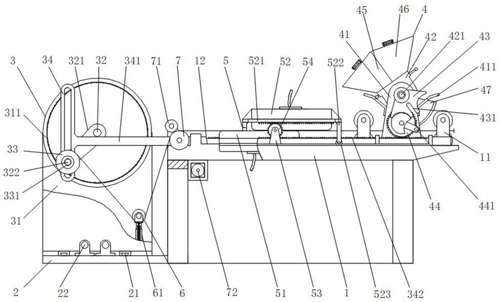
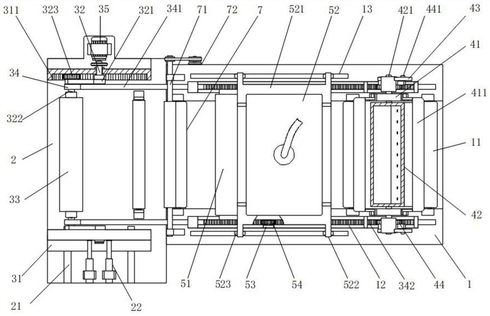

Image

  • Textile fabric processing equipment
  • Textile fabric processing equipment
  • Textile fabric processing equipment

Examples


Embodiment approach

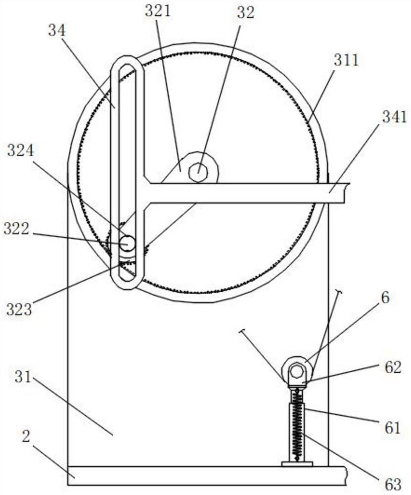
[0038] The specific embodiment is as follows: by slidingly connecting one of the support plates 31 to the top of the bottom plate 2, and then controlling the outward movement of one of the support plates 31 through the hydraulic rod 22, the two support plates 31 can be driven away from each other, and the cloth rolling roller 33 is provided with an insertion hole 331 to engage with the two retracting card shafts 322, and the engagement of the fixed key and the keyway 324 is used to realize the circumferential fixation of the cloth rolling roller 33, and then after the two support plates 31 are separated, , the cloth rolling roller 33 can be removed, and the two ends of the insertion hole 331 of the new cloth rolling roller 33 can also be inserted into the two retracting card shafts 322, and the hydraulic rod 22 is driven to push the support plate 31 to move inwards to realize alignment. The fixing of the cloth roll 33 can continue new processing, thereby greatly facilitating th...


PUM


Abstract

The invention discloses textile fabric processing equipment. The textile fabric processing equipment comprises a rack, wherein a bottom plate is fixedly mounted at the bottom of one end of the rack; adriving winding mechanism is arranged at the top of the bottom plate; a material mixing and coating mechanism is arranged at one end, far away from the bottom plate, of the top of the rack; supporting rollers are arranged at two sides of the material mixing and coating mechanism; the supporting rollers are mounted at the inner side of the top of the rack; an ironing mechanism is arranged at the top of the rack; the driving winding mechanism comprises two supporting plates; the two supporting plates are mounted at the top of the bottom plate; a gear disc is arranged at the inner side of the top of each supporting plate; and the middle part of each gear disc is in rotary connection with a driving shaft. According to the textile fabric processing equipment disclosed by the invention, a transverse rod is driven to do continuous reciprocating motion through the sliding of a winding clamping shaft and a vertical sliding groove plate; and the functions of automatically preparing, mixing andcoating are realized and a sufficient ironing function of fabric is also realized, so that the processing efficiency of blank fabric processing is greatly improved.

Description

technical field [0001] The invention relates to the technical field of cloth processing, in particular to a textile cloth processing equipment. Background technique [0002] Cloth is an indispensable material in people's life. According to the weaving method, there are two types of weft-knitted fabrics and warp-knitted fabrics. Weft-knitted fabrics are often made of low-elastic polyester yarn or special-shaped polyester yarn, nylon yarn, cotton yarn, Wool yarn, etc. are used as raw materials, using flat stitch, variable flat stitch, rib plain stitch, double rib plain stitch, jacquard stitch, terry stitch, etc., woven on various weft knitting machines. With the development of science and technology, The processing efficiency of cloth is also getting higher and higher; [0003] The prior art has the following disadvantages: in the cloth mechanism, it is necessary to apply a certain amount of treatment agent to the cloth, or a mixture of various treatment effects, such as a mi...

Claims


Application Information

Patent Timeline
Patent Type & Authority Applications(China)
IPC IPC(8): D06B1/12D06B23/20D06C15/10D06B23/04B65H23/188B65H19/30
CPCB65H19/30B65H23/1888B65H2701/1133D06B1/12D06B23/04D06B23/20D06B23/205D06C15/10
Inventor 张萍
Owner 张萍
Learn More