Kitchen waste oil-water separation device
An oil-water separation device and a technology for kitchen waste, applied in the directions of water/sewage multi-stage treatment, heating water/sewage treatment, water/sludge/sewage treatment, etc., can solve problems such as pipeline blockage and poor oil-water separation effect, and achieve Facilitate oil-water separation and complete oil-water separation
- Summary
- Abstract
- Description
- Claims
- Application Information
AI Technical Summary
Problems solved by technology
Method used
Image
Examples
Embodiment 1
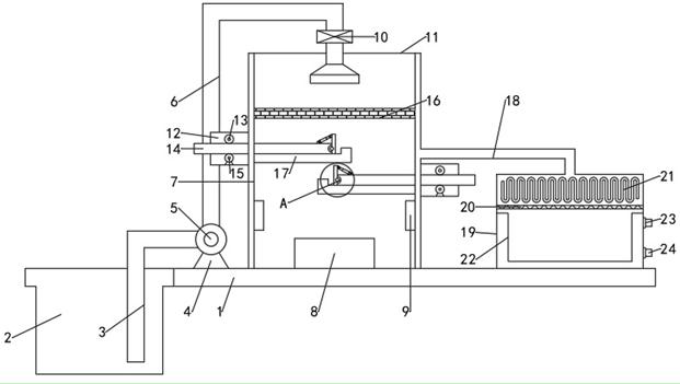
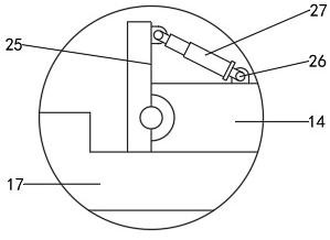
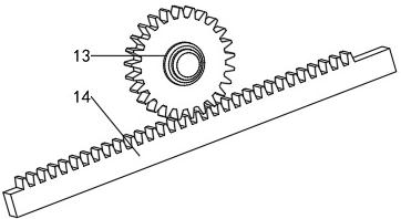
[0019] see Figure 1-3 , an oil-water separation device for food waste, comprising a base 1, a separation chamber 7 is fixed on the upper end surface of the base 1, a waste collection pool 2 is arranged on one side of the separation chamber 7, and the upper and lower ends of the separation chamber 7 are equipped with The sealing cover plate 11, the upper end of the base 1 is equipped with a pump 5 through the mounting seat 4, one side of the pump 5 is connected with the garbage collection pool 2 through the suction pipe 3, and the suction pipe 3 extends into the garbage collection At the inner bottom of the pool 2, a bent feeding pipe 6 is connected to the pump 5, and the end of the feeding pipe 6 away from the pump 5 extends through the sealing cover plate 11 at the upper end of the separation chamber 7 to the inside of the separation chamber 7 , the feeding check valve 10 is installed on the feed pipe 6; the inside of the separation chamber 7 is equipped with a first filter ...
Embodiment 2
[0028] In the embodiment, by using the property that the boiling point of edible oil is higher than that of water, the water is vaporized by heating the oil-water mixture and finally liquefied into water in the liquefaction chamber 19, which is convenient for recycling; The water still has waste heat that can be used, therefore, this embodiment is improved on the basis of Embodiment 1, and the improvement is: a heat exchange layer 22 is arranged in the liquefaction chamber 19, and the heat exchange layer 22 is located on the liquid outlet network 20 Below the liquefaction chamber 19, a return pipe 23 and a water inlet pipe 24 are arranged at intervals to communicate with the heat exchange layer 22. The water recycles the waste heat of the liquefaction chamber 19 and is also beneficial for the condenser 21 to cool the water vapor.
PUM
 Abstract
Description
Claims
Application Information
 - R&D Engineer
- R&D Manager
- IP Professional
- Industry Leading Data Capabilities
- Powerful AI technology
- Patent DNA Extraction
Browse by: Latest US Patents, China's latest patents, Technical Efficacy Thesaurus, Application Domain, Technology Topic, Popular Technical Reports.
© 2024 PatSnap. All rights reserved.Legal|Privacy policy|Modern Slavery Act Transparency Statement|Sitemap|About US| Contact US: help@patsnap.com


