
A device for removing residual sand in the inner cavity of castings by air flow

A casting inner cavity and residual sand technology, which is applied to the used abrasive processing device, vibration device, explosion generating device, etc., can solve the problems of difficult cleaning, air pollution, lack of cleaning methods, etc., and achieve vibration and friction frequency acceleration , improve the service life, and cover a wide area

Active Publication Date: 2022-01-28
苏州勤堡精密机械有限公司
View PDF15 Cites 0 Cited by
  • Summary
  • Abstract
  • Description
  • Claims
  • Application Information

AI Technical Summary

Problems solved by technology

However, due to the various performances of the coating, the results are different due to different emphases. When the coating has good collapsibility, the coating layer is easy to fall off during the vibration of the falling sand. Together, it adheres to the surface of the casting, and it is not easy to fall off by using the traditional vibration process, forming a sticky sand in the inner cavity of the casting, which is not easy to clean
When there is sand sticking in the complex inner cavity of the casting, due to the lack of effective cleaning methods, the casting will eventually be scrapped, causing certain economic losses
[0003] However, the existing sand cleaning devices generally adopt the cleaning method of shot blasting. Although this cleaning method has high sand cleaning efficiency, the cleaning effect is average for castings with many bending angles in the cavity, the coverage is low, and the blasting The produced pellets cannot be recycled, which is likely to cause air pollution

Method used


Image

  • A device for removing residual sand in the inner cavity of castings by air flow
  • A device for removing residual sand in the inner cavity of castings by air flow
  • A device for removing residual sand in the inner cavity of castings by air flow

Examples


Embodiment Construction

[0024] The following will clearly and completely describe the technical solutions in the embodiments of the present invention with reference to the accompanying drawings in the embodiments of the present invention. Obviously, the described embodiments are only some, not all, embodiments of the present invention. Based on the embodiments of the present invention, all other embodiments obtained by persons of ordinary skill in the art without making creative efforts belong to the protection scope of the present invention.

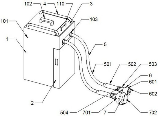
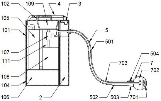
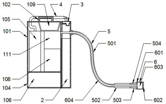
[0025] Please also refer to Figure 1-Figure 5 , wherein, a device that uses airflow to remove residual sand in the casting cavity includes a body 1, a sand storage device 2, a sealing device 3, an ultrasonic emission device 6 and a shot blasting device 7; the body 1 is provided with a connecting pipe 4 and The sealing device 3 is through-connected, the connecting pipe 4 is provided with two, and the two connecting pipes 4 are symmetrically arranged on the lef...


PUM


Abstract

The invention discloses a device for removing residual sand in the inner cavity of a casting by using airflow, which includes a body, a sand storage device, a sealing device, an ultrasonic emission device and a shot blasting device; the body is connected through a connection pipe to the sealing device , there are two connecting pipes, the two connecting pipes are symmetrically arranged on the left and right sides of the body, the sand storage device is movably clamped to the bottom end of the front of the body, and the sealing device is movably embedded in the body The top surface of the machine body, the machine body is connected with the ultrasonic emission device by being provided with a sand suction device, and the machine body is connected with the shot blasting device through the sand suction device. When the present invention is in use, it can comprehensively and thoroughly carry out sand cleaning treatment on the inside of the casting cavity, and can simultaneously absorb and store the pellets and residual sand during the residual sand cleaning process, so as to avoid scattering into the working space, and will not pollute the air.

Description

technical field [0001] The invention relates to the technical field of casting cleaning, in particular to a device for removing residual sand in the inner cavity of castings by using air flow. Background technique [0002] For castings with complex inner cavity structures, a layer of paint is mostly attached to the surface of the sand core to prevent sand sticking and improve surface roughness. However, due to the various performances of the coating, the results are different due to different emphases. When the coating has good collapsibility, the coating layer is easy to fall off by itself during the shakeout vibration process. At the same time, it adheres to the surface of the casting, and it is not easy to fall off using the traditional vibration process, forming a sticky sand in the inner cavity of the casting, which is not easy to clean. When there is sand sticking in the complex inner cavity of the casting, due to the lack of effective cleaning methods, the casting wi...

Claims


Application Information

Patent Timeline
Patent Type & Authority Patents(China)
IPC IPC(8): B24C3/06B24C9/00B24C5/00B24C5/04B22D31/00
CPCB24C3/06B24C9/00B24C9/006B24C5/005B24C5/04B22D31/002
Inventor 毛秀花李小巧
Owner 苏州勤堡精密机械有限公司
Learn More