
Marine waste treatment device

A technology for waste treatment and marine use, applied in the direction of grain treatment, etc., can solve the problems of closed storage and waste utilization, affect the ship environment, perishable and other problems, and achieve the effect of small environmental impact, improved utilization rate, and rapid crushing.

Inactive Publication Date: 2020-11-24
彭秀真
View PDF8 Cites 2 Cited by
  • Summary
  • Abstract
  • Description
  • Claims
  • Application Information

AI Technical Summary

Problems solved by technology

[0002] Ships inevitably directly or indirectly introduce some pollutants into the marine environment during driving, forming marine pollution. General solid waste contains a large amount of sewage, and it is easy to rot when it is directly packaged and stored, which affects the environment on the ship.
Chinese patent (publication number CN208116378U) discloses a marine waste treatment device, although it can solve the problem to a certain extent, but there are problems in safe crushing, filtering guide material, closed storage and waste utilization

Method used


Image

  • Marine waste treatment device
  • Marine waste treatment device
  • Marine waste treatment device

Examples


Embodiment 1

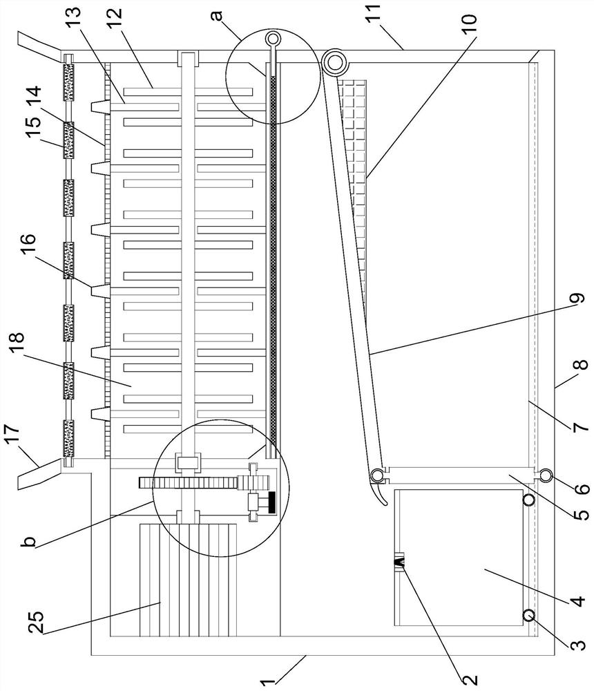
[0024] see Figure 1~4 , in an embodiment of the present invention, a marine waste treatment device includes a support installation plate 8 arranged horizontally, a support installation cylinder 1 is vertically arranged on the upper end of the support installation plate 8, and the right half of the upper end of the support installation cylinder 1 is vertically Straight out is provided with conical surface feeding cylinder 17, and the inner level of described conical surface feeding cylinder 17 is provided with passive rotation installation feeding structure, and the inner upper half part of supporting installation cylinder 1 is horizontally provided with filter material crushing structure, supports The lower half of the inside of the installation cylinder 1 is provided with a guide material storage structure. The passive rotation installation and feeding structure includes a rotation installation column symmetrically arranged front and back in the middle of the inner middle of ...

Embodiment 2

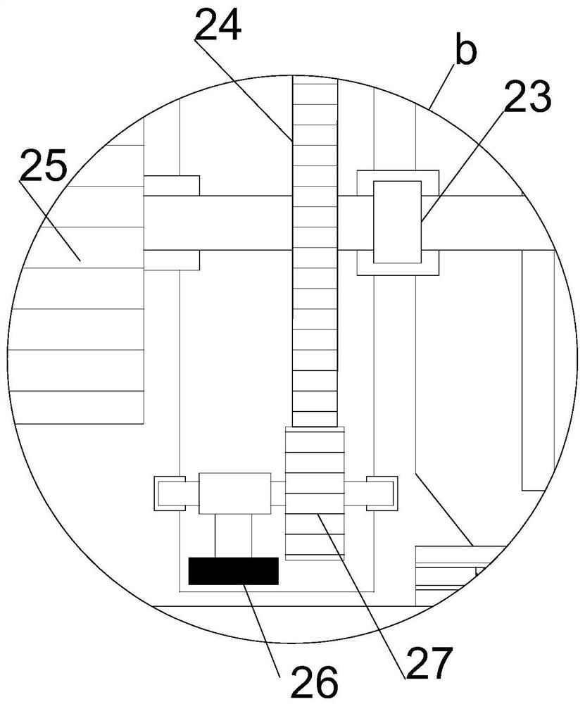
[0029] On the basis of Embodiment 1, through the driving gear 24 and the transmission gear 27 transmission ratio transmission, the high-speed rotation of the eccentric vibrating wheel 26 is realized, so that the whole device realizes vibration, greatly improving the speed of blanking, and the storage tank 4 is full The back cover is covered with a sealing cover plate. In the closed space on the lower side of the material guide plate 9, the gas generated is discharged through the overflow valve 2 and absorbed by the air cleaner 10. When it needs to be cleaned, or the fermentation has been completed, it can be directly The output is used, which greatly improves the utilization rate of waste, and has little impact on the environment.


PUM


Abstract

The invention relates to the field of marine devices, in particular to a marine waste treatment device. The device comprises a horizontally arranged support mounting plate. The upper end of the support mounting plate is vertically provided with a support mounting tube. The upper right half of the support mounting tube extends vertically and is provided with a conical surface feeding cylinder. Theinner part of the conical surface feeding cylinder is horizontally provided with a passive rotating mounting feeding structure. The inner upper half of the support mounting tube is horizontally provided with a filter material crushing structure. The inner lower half of the support mounting tube is provided with a guide material storage structure. The condition that feeding and crushing do not affect each other is realized through rotation and resetting, and cleanliness and safety of a work area is ensured. The dislocation crushing and interchangeable replacement of filter plates make crushingrapid and more adaptable. The high-speed rotation of an eccentric vibrating wheel makes the entire device vibrate, and greatly increases the speed of blanking. The closed fermentation greatly improvesthe utilization rate of waste, and has a small environmental impact.

Description

technical field [0001] The invention relates to the field of marine equipment, in particular to a marine waste treatment device. Background technique [0002] Ships will inevitably directly or indirectly introduce some pollutants into the marine environment during driving, forming marine pollution. General solid waste contains a large amount of sewage, which is easy to rot when it is directly packaged and stored, and affects the environment on the ship. Chinese patent (notification number CN208116378U) discloses a marine waste treatment device, although it can solve the problem to a certain extent, but there are problems in safe crushing, filtering and guiding materials, closed storage and waste utilization. [0003] In order to solve the above problems, the present invention is proposed, which realizes that feeding and crushing do not affect each other by rotating and resetting, which ensures the cleanliness and safety of the working area, and replaces the filter plate thro...

Claims


Application Information

Patent Timeline
Patent Type & Authority Applications(China)
IPC IPC(8): B02C13/06B02C13/26B02C13/286B02C23/16
CPCB02C13/06B02C13/26B02C13/286B02C23/16B02C2013/28618B02C2023/165B02C2201/06
Inventor 彭秀真
Owner 彭秀真
Learn More