
Preparation method of GMR magnetic field sensor

A magnetic field sensor, non-magnetic technology, applied in the field of magnetic field detection, can solve the problems of sensor sensitivity decrease, magnetoresistance change rate decrease, magnetic moment direction reversal, etc., to achieve improved measurement range, low hysteresis, high magnetic resistance value and The effect of sensitivity

Active Publication Date: 2020-11-20
珠海多创科技有限公司
View PDF12 Cites 1 Cited by
  • Summary
  • Abstract
  • Description
  • Claims
  • Application Information

AI Technical Summary

Problems solved by technology

The current AMR magnetic field sensor preparation process requires multiple growth and annealing to obtain the GMR effect to improve the linearity of the device and reduce the hysteresis. However, the annealing temperature in the existing process is mostly between 260 and 280 ° C. The higher annealing temperature brings the following disadvantages: 1. High temperature will lead to the diffusion of antiferromagnetic material atoms in the pinned layer of GMR film, and the ferromagnetic layer will be affected by this, which will lead to a decrease in the rate of change of magnetoresistance; 2. The annealing temperature is very close to The blocking temperature of the antiferromagnetic material can easily cause the direction of the magnetic moment to reverse, so that the direction of the magnetic moment of the pinning layer is not along the direction of the required test magnetic field
The above two points will lead to a decrease in the sensitivity of the sensor

Method used


Image

  • Preparation method of GMR magnetic field sensor
  • Preparation method of GMR magnetic field sensor
  • Preparation method of GMR magnetic field sensor

Examples


Embodiment Construction

[0030] In order to make the above and other objects, features and advantages of the present invention more apparent, the following specifically cites the embodiments of the present invention, together with the accompanying drawings, for a detailed description as follows.

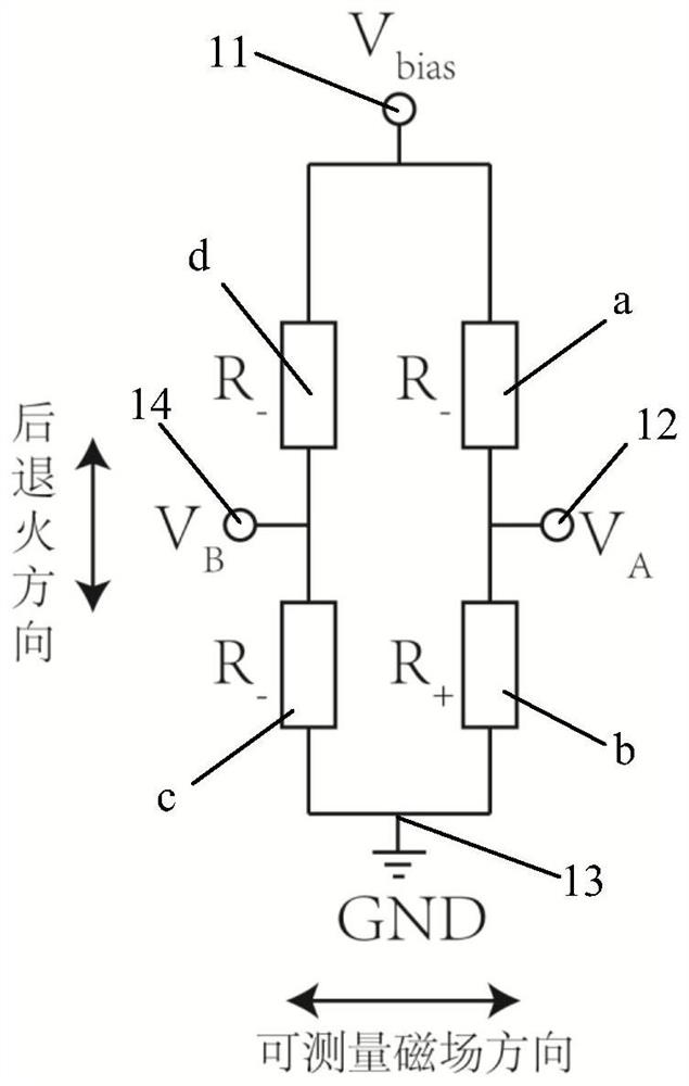
[0031] Such as figure 1 As shown, the full-bridge GMR magnetic field sensor includes 4 bridge-connected GMR magnetoresistive chips (a, b, c, d) with opposite resistance changes. Each GMR magnetoresistive chip can be an independent GMR magnetoresistive unit Or include a plurality of interconnected GMR magneto-resistive units. Each bridge arm in the full-bridge structure is respectively provided with a GMR magnetoresistive chip, and electrodes are arranged between adjacent GMR magnetoresistive chips, that is, there are two pairs of oppositely arranged electrodes (11, 12, 13, 14), One pair is input electrodes (11, 13), and the other pair is output electrodes (12, 14). When a constant voltage V is applied betwe...


PUM

PropertyMeasurementUnit
thicknessaaaaaaaaaa
thicknessaaaaaaaaaa
thicknessaaaaaaaaaa

Abstract

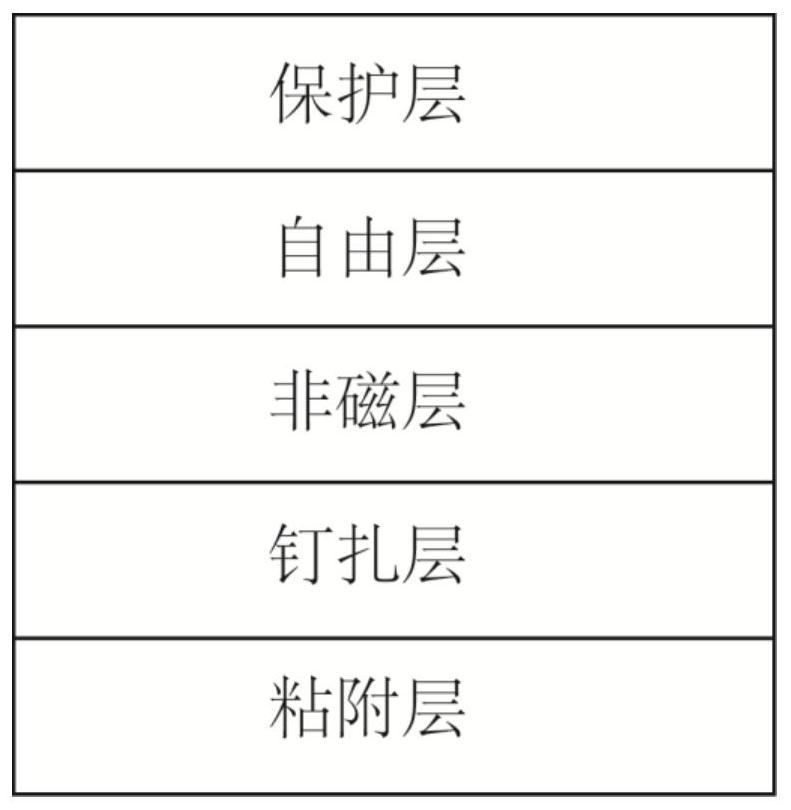
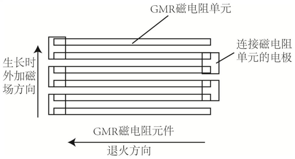
The invention discloses a preparation method of a GMR magnetic field sensor. The preparation method comprises the steps of providing a substrate; depositing a GMR multilayer film structure on the substrate, wherein the GMR magnetoresistance unit at least comprises a pinning layer, a non-magnetic metal layer and a free layer; applying an external magnetic field to magnetize the pinning layer whiledepositing the GMR multilayer film structure; carrying out low-temperature magnetic annealing, wherein the annealing direction is perpendicular to the magnetization direction of the pinning layer, andthe annealing temperature is lower than the blocking temperature of an antiferromagnetic material in the pinning layer; forming mutually independent GMR magnetoresistance chips on the GMR multilayerfilm structure; and connecting the GMR magnetoresistance chips according to a full-bridge structure, and connecting the GMR magnetoresistance chips with the input electrode and the output electrode toobtain the GMR magnetic sensor with the full-bridge structure. By adopting a low-temperature low-field annealing mode, the difficulty of temperature control is reduced, interlayer diffusion is inhibited, and the sensor can have higher magnetoresistance value and sensitivity.

Description

technical field [0001] The invention belongs to the technical field of magnetic field detection, and in particular relates to a preparation method of a GMR magnetic field sensor. Background technique [0002] Magnetic field sensors are widely used in modern measurement systems to measure or detect physical parameters, including magnetic field strength, direction, displacement, etc. There are many types of magnetic field sensors, such as Hall sensors, AMR magnetic field sensors, and GMR magnetic field sensors. The GMR magnetic field sensor uses the electron scattering effect between the magnetic multilayer films to detect the magnetic field, which shows that the resistance of the magnetic multilayer film material changes significantly with the magnitude and direction of the external magnetic field. Compared with the AMR magnetic field sensor, the GMR magnetic field sensor has a larger resistance change rate, and has better temperature stability than the Hall effect material....

Claims


Application Information

Patent Timeline
Patent Type & Authority Applications(China)
IPC IPC(8): G01R33/09G01R33/00
CPCG01R33/093G01R33/0052
Inventor 刘明胡忠强关蒙萌周子尧王立乾朱家训
Owner 珠海多创科技有限公司
Learn More