
Safety explosion-proof lamp for coal underground construction

An explosion-proof lamp, safety technology, applied in the direction of gas-proof/waterproof device, cooling/heating device of lighting device, lighting and heating equipment, etc., can solve problems such as heat dissipation difficulties, achieve lighting effects, promote rapid flow, and improve heat dissipation speed effect

Inactive Publication Date: 2020-11-20
左艳
View PDF0 Cites 1 Cited by
  • Summary
  • Abstract
  • Description
  • Claims
  • Application Information

AI Technical Summary

Problems solved by technology

[0005] The purpose of the present invention is to provide a safety explosion-proof lamp for underground coal mine construction with good heat dissipation effect for the problem of difficult heat dissipation.

Method used


Image

  • Safety explosion-proof lamp for coal underground construction
  • Safety explosion-proof lamp for coal underground construction

Examples


Embodiment 1

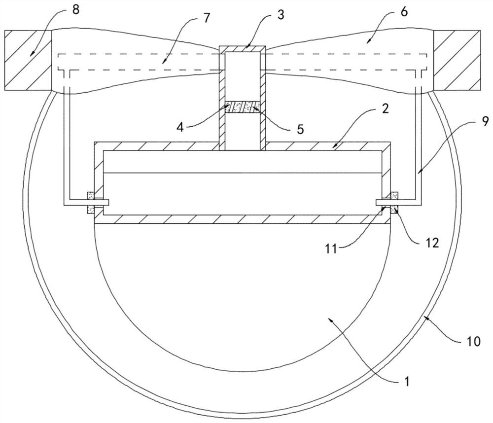
[0018] Such as figure 1 As shown, a safety explosion-proof lamp for underground coal mine construction includes a lamp body 1, the upper end of the lamp body 1 is fixedly connected with a coolant tank 2, the coolant tank 2 is filled with evaporating liquid, and the upper end of the coolant tank 2 is connected with The evaporating tube 3 is fixedly connected to the inner side wall of the evaporating tube 3 with a horizontally arranged turntable 4, and the turntable 4 is provided with a plurality of exhaust holes 5 through which it is arranged. It should be noted that the axial direction of the exhaust hole 5 and the horizontal plane The included angle is 30°, when the gaseous evaporating liquid passes through the vent hole 5, the impact force of the airflow will give a horizontal component force to the side wall of the vent hole 5, and the inclination directions of multiple vent holes 5 are the same, and the component force is formed to drive The torsional force of the turntabl...

Embodiment 2

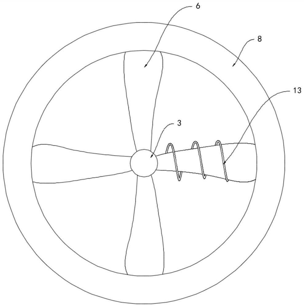
[0023] Such as figure 2 As shown, the difference between this embodiment and Embodiment 1 is that the fixed ring 8 is composed of semi-annular magnets with opposite magnetic poles at both ends, and a closed coil 13 is wound around one fan blade 6, and the winding direction of the closed coil 13 is It is perpendicular to the direction of the magnetic field lines of the fixed ring 8 .

[0024] In this embodiment, when the fan blade 6 drives the closed coil 13 to rotate, the closed coil 13 continuously cuts the magnetic field lines of the fixed ring 8, and an induced current is generated in the closed coil 13. According to the principle of electrostatic adsorption, the dust in the air will be absorbed It is adsorbed on the surface of the closed coil 13 to prevent dust from adhering to the surface of the lamp body 1 and the protective net 10 with the airflow, and to avoid affecting its lighting effect.


PUM


Abstract

The invention belongs to the field of LED lamps, and particularly relates to a safety explosion-proof lamp for coal underground construction. The lamp comprises a lamp body, wherein the upper end of the lamp body is fixedly connected with a cooling liquid tank, evaporation liquid is contained in the cooling liquid tank, the upper end of the cooling liquid tank is rotationally communicated with anevaporation pipe, the inner side wall of the evaporation pipe is fixedly connected with a horizontally-arranged rotary disc, a plurality of through exhaust holes are formed in the rotary disc, the plurality of exhaust holes are formed in an inclined manner, a plurality of fan blades which are arranged in an annular array are fixedly mounted at the upper end of the evaporation pipe, cooling channels communicated with the evaporation pipe are formed in the fan blades, the evaporation pipe is coaxially sleeved with a fixing ring, the ends, which are away from the evaporation pipe, of the fan blades are rotatably connected with the inner side wall of the fixing ring, and the side wall of the cooling liquid box is rotatably communicated with a plurality of return pipes. The evaporation liquid circularly flows in the cooling liquid tank, the evaporation pipe and the cooling channels, and a good heat dissipation and cooling effect can be achieved without other driving devices.

Description

technical field [0001] The invention belongs to the field of LED lamps, in particular to a safety explosion-proof lamp for underground coal mine construction. Background technique [0002] Explosion-proof lamps refer to lamps that are used in hazardous places where flammable gases and dust exist, and can prevent arcs, sparks and high temperatures that may be generated inside the lamp from igniting flammable gases and dust in the surrounding environment, thereby meeting explosion-proof requirements. [0003] Existing explosion-proof lamps for underground coal mine construction, because the lamp body needs to be sealed to prevent the entry of combustible gas, there is a common problem of heat dissipation. The sealing effect makes it difficult to play an explosion-proof role, and the LED lamp works at high temperature for a long time, which seriously reduces its service life, and even causes the risk of short circuit and explosion, and its safety performance is poor. [0004] ...

Claims


Application Information

Patent Timeline
IPC IPC(8): F21S8/00F21V17/10F21V29/56F21V29/67F21V31/00F21Y115/10
CPCF21S8/00F21V17/105F21V31/00F21V29/56F21V29/67F21Y2115/10
Inventor 左艳齐国友
Owner 左艳
Learn More