A vase changing device for ceramic manufacturing

A technology for vases and ceramics, which is applied in the field of vase opening equipment for ceramic manufacturing, which can solve the problems of high labor intensity and low efficiency, and achieve the effects of reducing operation difficulty, improving work efficiency, and ensuring bonding effect

Active Publication Date: 2021-12-03
潮州市潮安区卓越陶瓷有限公司
View PDF0 Cites 0 Cited by
  • Summary
  • Abstract
  • Description
  • Claims
  • Application Information

AI Technical Summary

Problems solved by technology

[0005] In order to overcome the shortcomings of high labor intensity, low efficiency and high technical requirements for workers in manual replacement of vase blanks, the technical problem to be solved by the present invention is to provide a method that can reduce the labor intensity of workers and improve work efficiency. High-efficiency vase-changing equipment for ceramics manufacturing with low technical requirements for workers

Method used


Image

  • A vase changing device for ceramic manufacturing
  • A vase changing device for ceramic manufacturing
  • A vase changing device for ceramic manufacturing

Examples


Embodiment 1

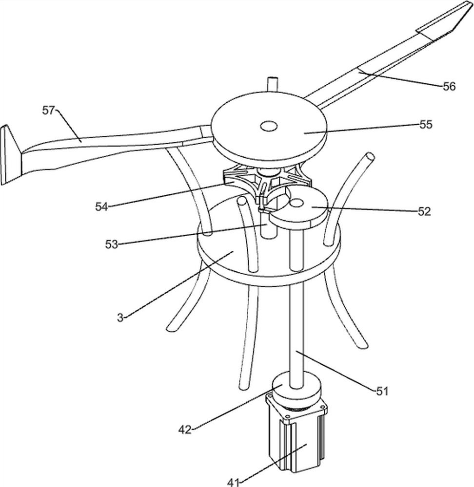
[0023] A device for changing mouths of vases for ceramic manufacture, such as Figure 1-3 As shown, it includes a stand 1, a support plate 2, a frame 3, a rotating assembly 4 and a replacement assembly 5, a support plate 2 is installed on the right side of the bottom of the stand 1, a frame 3 is connected to the right side of the top of the stand 1, and the stand 1 and the A rotating assembly 4 is installed between the support plates 2 , and a replacement assembly 5 is installed between the platform 1 and the frame 3 .

[0024] The rotating assembly 4 includes a reduction motor 41, a runner 42, a belt 43, a long rack 44, a short rack 45, a transmission gear 46, a rotating rod 47 and a first rotating disk 48, and the support plate 2 is connected with a reduction motor 41, and the stand 1 The left and right sides of the bottom are rotatably equipped with runners 42, the runner 42 on the right is connected to the output shaft of the reduction motor 41, a belt 43 is connected betw...

Embodiment 2

[0028] On the basis of Embodiment 1, as shown in 4, it also includes a brush assembly 6, and the brush assembly 6 includes a connecting rod 61, a dipping brush 62, a roller 63, a guide rail 64 and a charging bucket 65, the first The outer surface of the second turntable 55 is hingedly connected with a connecting rod 61, the tail end of the connecting rod 61 is connected with a dip brush 62 in a detachable manner, the bottom of the connecting rod 61 is connected with a roller 63, and the top of the frame 3 is connected with a guide rail 64, the roller 63 is in contact with the top surface of the guide rail 64, the rear side of the top of the stand 1 is connected with a charging bucket 65, and the rear portion of the guide rail 64 is concave.

[0029] Fill the charging barrel 65 with mud material for bonding. When the second turntable 55 rotates, the connecting rod 61 is driven to rotate, and the roller 63 rolls on the guide rail 64. When the roller 63 moves to the concave positi...


PUM


Abstract

The invention relates to ceramic manufacturing equipment, in particular to a vase mouth changing device for ceramic manufacturing. The technical problem to be solved by the present invention is to provide a device for changing mouths of ceramic vases that can reduce the labor intensity of workers, improve work efficiency and have lower technical requirements for workers. In order to solve the above-mentioned technical problems, the present invention provides such a device for changing mouths of vases for ceramic manufacturing, which includes a stand, one side of which is connected with a support plate; a frame, which is connected to one side of the top of the stand; a rotating assembly, which is connected to Between the stand and the support plate; the replacement component is connected between the stand and the frame. Through the cooperation of the rotating assembly and the replacement assembly, the invention does not need to cut the mouth of the vase body with a knife manually, which reduces the difficulty of operation and can automatically continue to scrape off excess mud.

Description

technical field [0001] The invention relates to ceramic manufacturing equipment, in particular to a vase mouth changing device for ceramic manufacturing. Background technique [0002] At present, the replacement of the vase body is usually done manually. Manually, the vase body needs to be placed on the turntable. First, the mouth of the vase body is cut off, and then the cut end is brushed and glued After receiving the mud, the unnecessary mud on the vase body is removed by manual hand-held cutters. The labor intensity of the workers in the above-mentioned operation mode is high, the efficiency is low, and the technical requirements for the workers are relatively high. [0003] Therefore need to research and develop a kind of can reduce worker's labor intensity, improve work efficiency and lower to the worker's technical requirement the pottery vase mouth-changing equipment for making. Contents of the invention [0004] (1) Technical problems to be solved [0005] In or...

Claims


Application Information

Patent Timeline
Patent Type & Authority Patents(China)
IPC IPC(8): B28B11/12B28B11/02
CPCB28B11/02B28B11/12
Inventor 不公告发明人
Owner 潮州市潮安区卓越陶瓷有限公司
Why Eureka
Try Eureka