
An integrated forming pipe bending device for bulging pipe bending

A pipe bending device and an integrated technology, applied in the field of bulging pipe manufacturing, can solve the problems of resource sharing, low labor production efficiency, resource waste, etc., and achieve high production efficiency, shortened production cycle, and high yield. Effect

Active Publication Date: 2020-12-18
浙大宁波理工学院
View PDF6 Cites 0 Cited by
  • Summary
  • Abstract
  • Description
  • Claims
  • Application Information

AI Technical Summary

Problems solved by technology

At present, a forming device and a bending device (automatic or manual) are needed in the manufacturing process of the bulging bend to realize the two actions of bulging and bending of the pipe to be processed respectively. It is irrelevant, and the devices that realize these two actions are also independent of each other, and the effect of resource sharing cannot be achieved, the labor production efficiency is low, and the waste of resources is serious
In addition, if the two actions of bulging and bending are performed on two different equipments, after the bulging process is completed, a transfer of the pipe is bound to be carried out, and the transfer of the pipe from the bulging equipment to the bending equipment requires an additional time. The taking and placing of the pipe, that is, taking it off from the clamping device of the bulging equipment, and then assembling it on the clamping device of the bending equipment, these two actions not only need a certain amount of time to complete, but also the pipe is in the process of transferring There is also a risk of damage in

Method used


Image

  • An integrated forming pipe bending device for bulging pipe bending
  • An integrated forming pipe bending device for bulging pipe bending
  • An integrated forming pipe bending device for bulging pipe bending

Examples


Embodiment

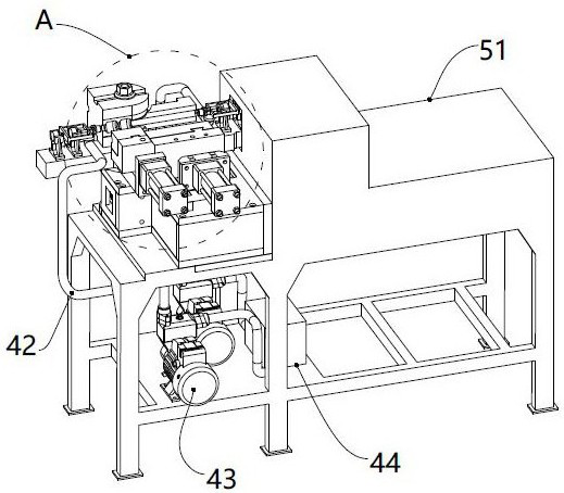
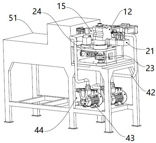
[0028] Embodiment: a kind of integral forming pipe bending device of bulging pipe, the structure is as follows Figure 1 to Figure 3 As shown, it includes a mold set, a pipe bending mechanism, a hydraulic system and a sealing mechanism arranged at both ends of the mold set; the mold set is used for clamping and bulging of the pipe to be processed, and the hydraulic system provides bulging for the pipe to be processed Internal pressure; the mold set includes a first mold 11 and a second mold 12 which are arranged oppositely; the structure of the bending mechanism is as Figure 7 , 8 As shown, it includes a rotatable bending arm 21. The bending arm 21 is in the shape of "L" as a whole, and the horizontal and vertical intersections of the "L" shape are its turning points. When the bending arm 21 rotates, it drives the first mold 11 and the second mold 11. The mold 12 rotates synchronously; the second mold 12 is provided with an elbow groove 121, and the structure is as Figure ...


PUM


Abstract

The invention discloses an integrated forming and pipe-bending device for bulging and pipe-bending. The integrated forming and pipe-bending device for bulging and pipe-bending comprises a die group, apipe-bending mechanism, a hydraulic system and sealing mechanisms arranged at the two ends of the die group, wherein the die group is used for clamping and bulging for a pipe to be machined; the hydraulic system provides a bulging inner pressure for the pipe to be machined; the die group comprises a first die and a second die which are oppositely arranged; the pipe-bending mechanism comprises a rotatable bending arm, and the bending arm drives the first die and the second die to synchronously rotate while rotating; a pipe-bending groove is formed in the second die, and acts on the pipe to bend the pipe along with the rotation of the second die; and each sealing mechanism comprises a plug head sealing the end part of the pipe, and when the pipe is bent, the plug heads synchronously move along with the movement of the end part of the pipe. The integrated forming and pipe-bending device for bulging and pipe-bending realizes the double action of bulging and pipe-bending on one piece of equipment, and then realizes resource sharing and increases the production efficiency; and the manufacturing period for the bent pipe manufactured by the device is shortened, and a high yield is achieved.

Description

technical field [0001] The invention relates to the technical field of manufacturing bulging pipes, in particular to an integrally formed pipe bending device for bulging pipes. Background technique [0002] The pipes produced by internal high-pressure bulging, such as bellows, are widely used as pipes for conveying fluids. In practical applications, the bulging pipes generally need to be bent to be processed into curved pipes with a certain degree of curvature. , to meet the usage requirements. At present, a forming device and a bending device (automatic or manual) are needed in the manufacturing process of the bulging bend to realize the two actions of bulging and bending of the pipe to be processed respectively. It is irrelevant, and the devices that realize these two actions are also independent of each other, so the effect of resource sharing cannot be achieved, the labor production efficiency is low, and the waste of resources is serious. In addition, if the two actio...

Claims


Application Information

Patent Timeline
Patent Type & Authority Patents(China)
IPC IPC(8): B21D26/047B21D26/049B21D26/045B21D26/041B21D15/10B21D9/07B21D9/15B21D37/10
CPCB21D9/073B21D9/15B21D15/10B21D26/041B21D26/045B21D26/047B21D26/049B21D37/10
Inventor 张峰陈怡江刘文张池王春鸽郑浩民王沛超滕叶莹林立应祺辉
Owner 浙大宁波理工学院
Learn More