
Synchronous rectification device and method for isolated power supply

A technology of power supply synchronization and rectification device, applied in the direction of output power conversion device, electrical components, regulating electrical variables, etc., can solve problems such as large power consumption, secondary side short circuit, circuit damage, etc. The effect of reducing conduction loss and improving safety

Pending Publication Date: 2020-11-17
SHANGHAI BAIGONG SEMICON CO LTD
View PDF0 Cites 1 Cited by
  • Summary
  • Abstract
  • Description
  • Claims
  • Application Information

AI Technical Summary

Problems solved by technology

[0003] The traditional synchronous rectification device has the following technical defects: the rectifier diode is generally used on the secondary side, and the power consumption of the rectifier diode in the on state is large, so the conversion efficiency loss of the isolated power supply is serious; at the same time, in all synchronous In the rectified isolated power supply, because negative current may be generated in the circuit, this will lead to the phenomenon of current backflow, that is, the current may flow from the output side to the input side, so it is easy to cause a short circuit on the primary side / secondary side. damage to the circuit
[0004] Therefore, it is necessary to solve the technical problems of low conversion efficiency, current backflow, and short circuit of the isolated power supply

Method used


Image

  • Synchronous rectification device and method for isolated power supply
  • Synchronous rectification device and method for isolated power supply
  • Synchronous rectification device and method for isolated power supply

Examples


Embodiment Construction

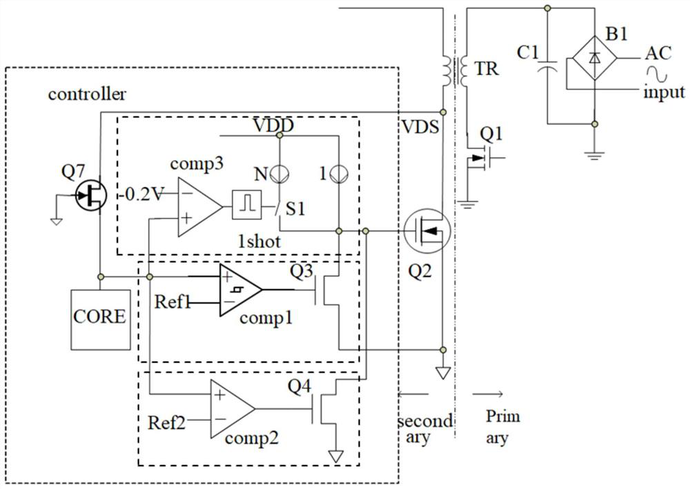
[0042] In order to more clearly illustrate the embodiments of the present invention or the technical solutions in the prior art, the specific implementation manners of the present invention will be described below with reference to the accompanying drawings. Obviously, the accompanying drawings in the following description are only some embodiments of the present invention, and those skilled in the art can obtain other accompanying drawings based on these drawings and obtain other implementations.

[0043] In order to make the drawing concise, each drawing only schematically shows the parts related to the present invention, and they do not represent the actual structure of the product. In addition, to make the drawings concise and easy to understand, in some drawings, only one of the components having the same structure or function is schematically shown, or only one of them is marked. Herein, "a" not only means "only one", but also means "more than one".

[0044] An isolate...


PUM


Abstract

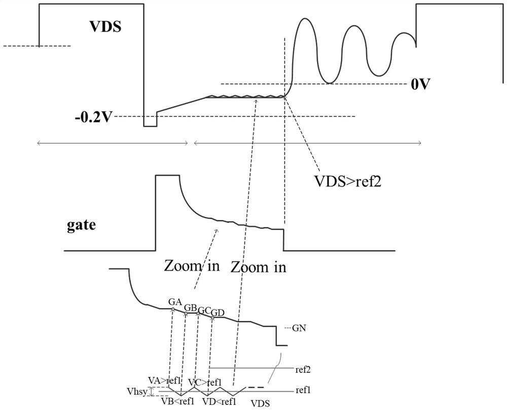
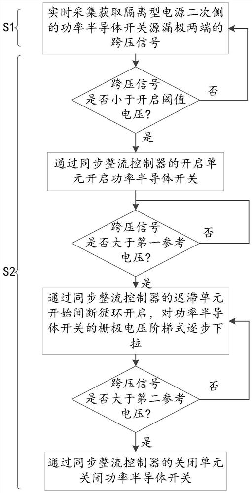
The invention discloses a synchronous rectification device and method for an isolated power supply, and the device comprises a power semiconductor switch and a synchronous rectification controller, and a reference grounding end of the isolated power supply is connected with a reference ground through the source and drain electrodes of the power semiconductor switch. In the synchronous rectification controller, a control unit receives the voltage-crossing signals at the two ends of the source electrode and the drain electrode of the power semiconductor switch, separately controls a switching-onunit and a switching-off unit to switch on and off the power semiconductor switch according to the voltage-crossing signals, and controls a hysteresis unit to be switched on discontinuously and circularly so as to gradually pull down the grid voltage of the power semiconductor switch in a stepped mode. According to the present invention, the technical problems of low conversion efficiency, current backflow and short circuit of the isolated power supply are solved, the power semiconductor switch can be quickly turned on and turned off, the gate voltage of the power semiconductor switch is gradually reduced in a stepped manner, and the switch is directly turned off when the gate voltage approaches to a cut-off threshold voltage, so that the current backflow is reduced, and the opportunity of primary / secondary side short circuit is reduced.

Description

technical field [0001] The invention belongs to the field of power supply technology, and in particular relates to an isolated power supply synchronous rectification device and method. Background technique [0002] The isolated power supply is a power supply device based on magnetic components such as a transformer. The external power supply is converted into an internal power supply through the transformer, and the external power supply is isolated. The transformer has a primary side and a secondary side, and the primary side is used to access the external power supply. , the secondary side is used to output the internal power supply to the load. At the same time, in order for the internal power supply to meet the power supply requirements, it is also necessary to perform synchronous rectification on the internal power output from the secondary side. [0003] The traditional synchronous rectification device has the following technical defects: the rectifier diode is general...

Claims


Application Information

Patent Timeline
IPC IPC(8): H02M1/08H02M7/217H02M3/335H02M1/32
CPCH02M1/08H02M1/32H02M3/33592H02M7/217Y02B70/10
Inventor 徐健国
Owner SHANGHAI BAIGONG SEMICON CO LTD
Learn More