Buried recharge well and recharge system suitable for sponge city
A sponge city and recharge well technology, applied in drinking water installations, general water supply conservation, water/sludge/sewage treatment, etc., can solve problems such as the inability to quickly store rainwater geological changes, etc., to promote excretion, promote circulation, reduce The effect of surface runoff
- Summary
- Abstract
- Description
- Claims
- Application Information
AI Technical Summary
Problems solved by technology
Method used
Image

Examples
Embodiment 1
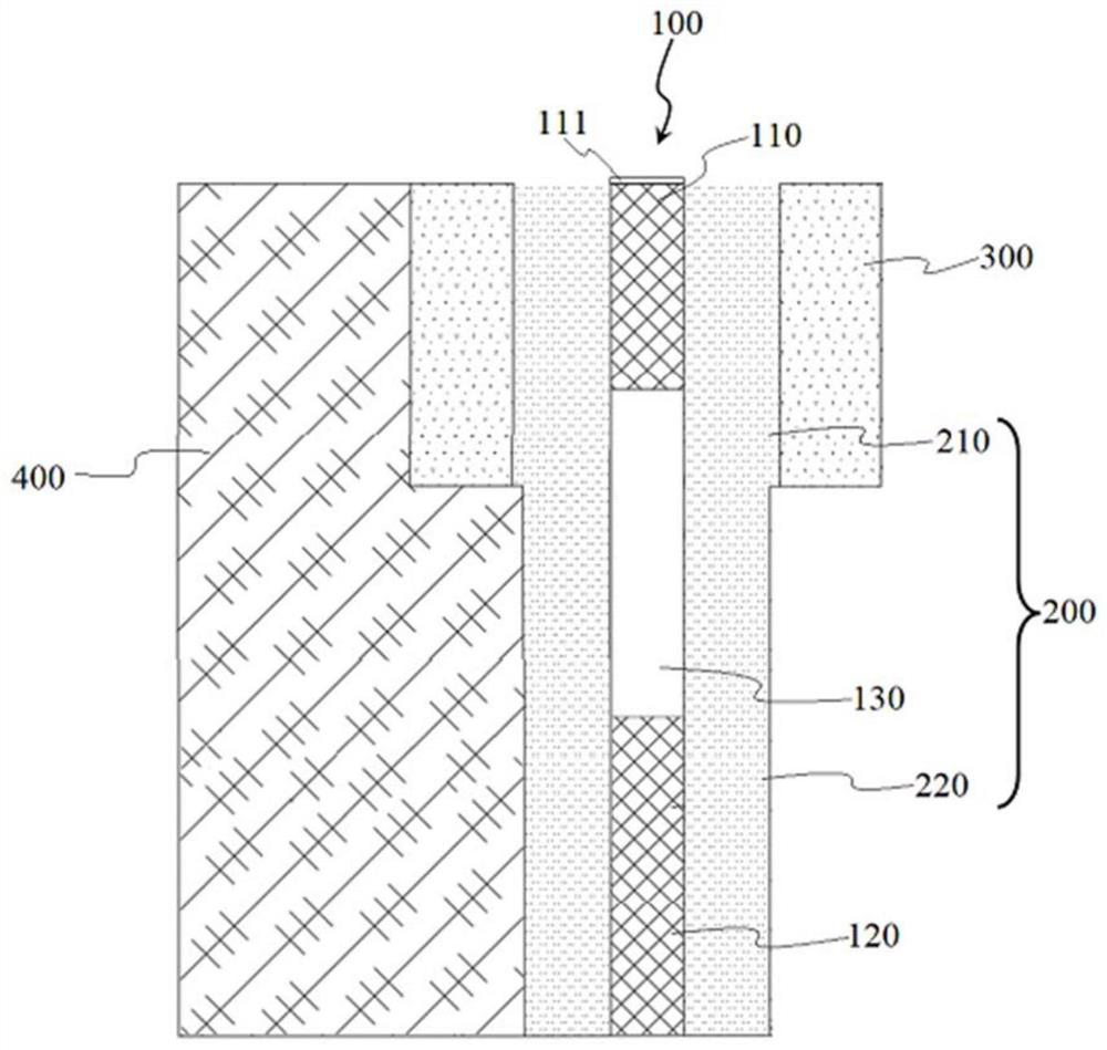
[0039] Such as figure 1 As shown in Figure 2, a buried recharge well of the present invention, the outside of the buried recharge well is a miscellaneous fill layer 400, and the buried recharge well includes a recharge well pipeline 100, a fine sand layer 200 and a gravel layer 300, the reinjection well pipeline 100 is set in the aquifer, the diameter of the reinjection well pipeline 100 is d1, the permeability of the surface soil is tested by sampling, according to the on-site storage of rainwater and the geological structure of the natural aquifer, flexible selection The location and design of the project should be in accordance with the local geological conditions, which can not only store rainwater, but also avoid damage to the road. The hydrogeological conditions of the buried reinjection well in this example mainly exist two aquifers from top to bottom, which are the phreatic aquifer and the first confined aquifer respectively. The aquifer referred to in this example is ...
Embodiment 2
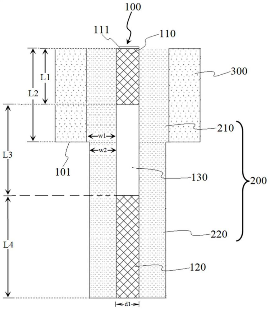
[0049] The content of this embodiment is basically the same as that of Embodiment 1, the difference is that a buried reinjection well of the present invention includes a reinjection well pipeline 100, a fine sand layer 200 and a gravel layer 300, and the reinjection well pipeline 100 is connected with a water-containing The reinjection well pipeline 100 has a diameter d1 of 1.1m. The reinjection well pipeline 100 is provided with an upper seepage section 110, a water guide section 130, and a seepage lower section 120 in sequence from top to bottom, wherein the seepage upper section of the reinjection well pipeline 100 The radial depth L1 of 110 is 0.5m, the radial depth L3 of the water guiding section 130 is 1m, the radial depth of the seepage lower section 120 is deeper than the radial depth of the water guiding section 130, and the radial depth of the seepage lower section 120 in this embodiment L4 is 1.5m.
[0050] The reinjection well pipeline 100 is provided with a fine s...
Embodiment 3
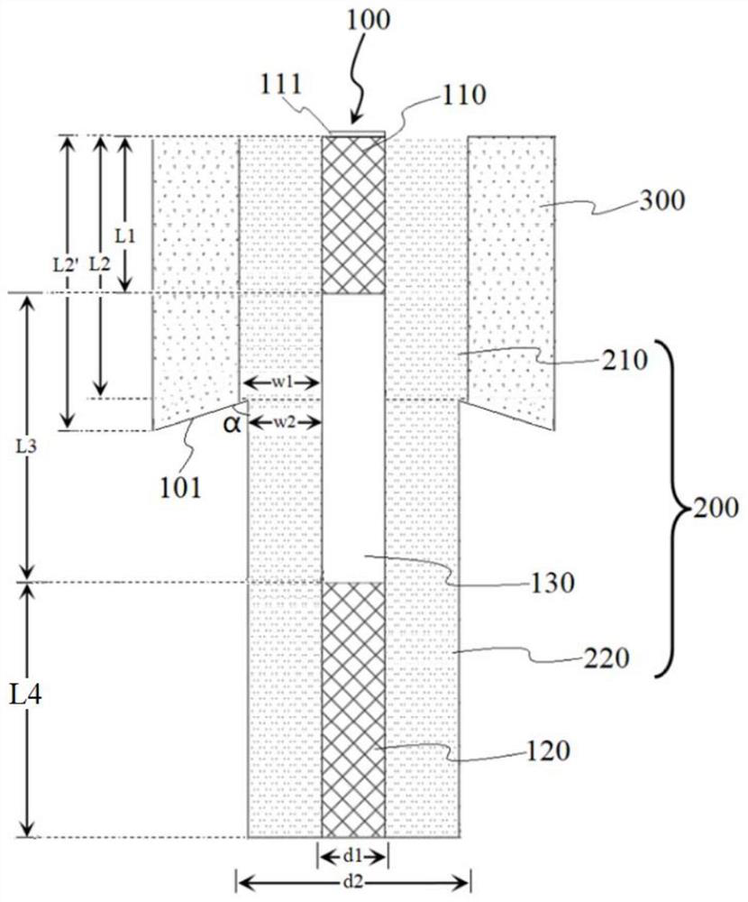
[0052] The content of this embodiment is basically the same as that of Embodiment 1, except that in a buried reinjection well of the present invention, the radial depth of the upper section 210 of the fine sand layer is L2, and the diameter of the seepage upper section 110 of the reinjection well pipeline 100 is The depth is L1, L1 Figure 2b shown), that is, the radial depth of the gravel layer 300 near the upper section 210 of the fine sand layer is L2, and the radial depth of the gravel layer 300 near the sidewall of the well body is L2', and L2'>L2. By setting the height of the step surface 101 close to the side of the reinjection well pipeline 100 to be lower than the height of the bottom of the seepage upper section 110, the gravel of the gravel layer 300 can be prevented from floating under the impact of rainwater and colliding with the fine sand layer 200. The fine sand is mixed, so that the gravel layer 300 and the fine sand layer 200 can better cooperate with each othe...
PUM
| Property | Measurement | Unit |
|---|---|---|
| Horizontal width | aaaaa | aaaaa |
| Horizontal width | aaaaa | aaaaa |
| Radial depth | aaaaa | aaaaa |
Abstract
Description
Claims
Application Information
 - R&D
- Intellectual Property
- Life Sciences
- Materials
- Tech Scout
- Unparalleled Data Quality
- Higher Quality Content
- 60% Fewer Hallucinations
Browse by: Latest US Patents, China's latest patents, Technical Efficacy Thesaurus, Application Domain, Technology Topic, Popular Technical Reports.
© 2025 PatSnap. All rights reserved.Legal|Privacy policy|Modern Slavery Act Transparency Statement|Sitemap|About US| Contact US: help@patsnap.com