Electric shaver

An electric shaver, active technology, applied in the direction of metal processing, etc., can solve the problems of increased noise, sealing ring leakage, increased load, etc., to achieve the effects of prolonged service life, good sealing performance, and excellent waterproof effect

Active Publication Date: 2020-11-17
HUANXING TECH HANGZHOU CO LTD
View PDF8 Cites 0 Cited by
  • Summary
  • Abstract
  • Description
  • Claims
  • Application Information

AI Technical Summary

Problems solved by technology

The disadvantages of this method are obvious: increased noise, increased load, and the seal ring is required to seal the pivot shaft. Long-term use will cause leakage of the seal ring after aging and wear.
[0003] There is also an electric shaver, such as the structure disclosed in reference document 1 (201820512427.3), which adopts a magnetic attraction method to connect the hand-held part and the cutter head part, such as figure 1 As shown, it includes the motor 10 located on the central axis, and the upper magnet 30 located on the upper part, and the lower magnet 20 located on the lower part. Through this magnetic attraction method, the hand-held part and the cutter head part are connected to solve the problem of aging and wear of the sealing ring. Leakage occurs; but this assembly method also brings new problems, because the upper magnet and the lower magnet are arranged on the central axis of the electric shaver, and the motor needs to function as the lower magnet, that is, the output shaft of the motor is directly connected to the lower magnet. Magnet connection, that is, it must be ensured that the motor is also set on the central axis of the electric shaver,

Method used


Image

  • Electric shaver
  • Electric shaver
  • Electric shaver

Examples


Embodiment 1

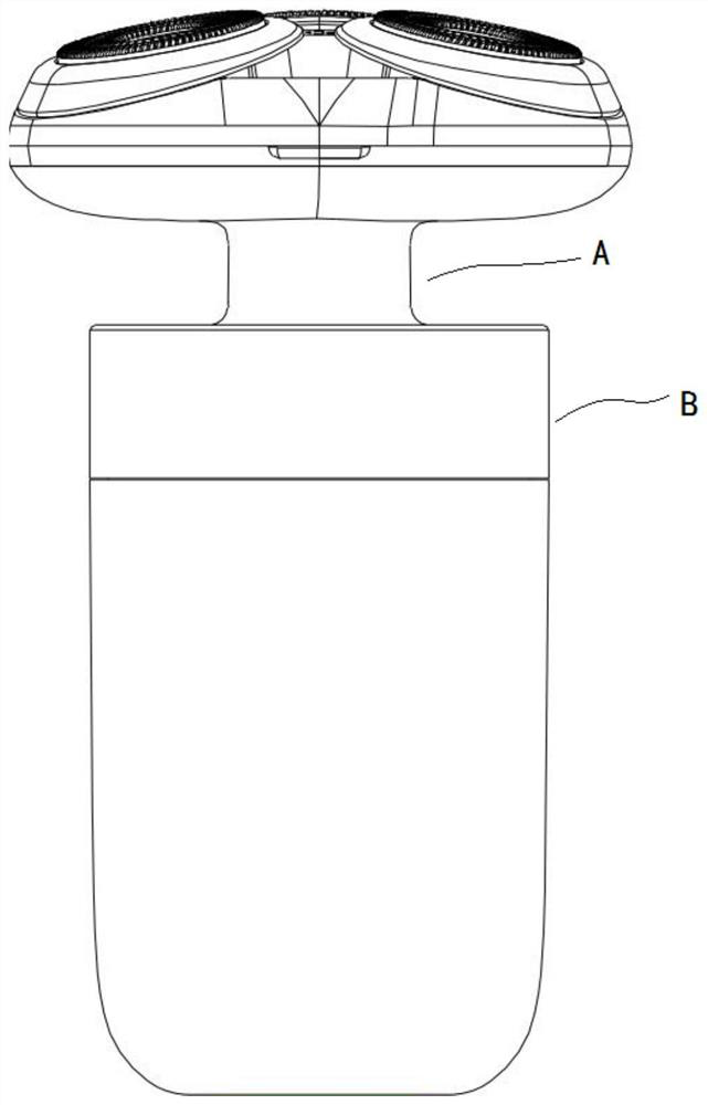
[0044] refer to Figure 2-Figure 4 As shown, an electric shaver includes a main body assembly and a head cover assembly. The head cover assembly is arranged on the main body assembly. unit, the head cover assembly includes a moving knife unit and an upper casing A for supporting the moving knife unit, the lower casing is embedded with an active magnetic assembly, and the upper casing is embedded with a driven magnetic assembly. The electric shaver When the knife is stationary and placed vertically, the magnetism corresponding to the longitudinal direction of the active magnetic assembly and the driven magnetic assembly is in a state of opposite sex attraction. Driven to rotate under the action of the assembly and the driven magnetic assembly; the central axis of the active magnetic assembly and the driven magnetic assembly coincides with the central axis of the electric shaver, and the central axis of the motor deviates from the electric shaver The central axis of 4-8cm (refe...

Embodiment 2

[0053] As shown in Embodiment 1, the assembly of the eccentric motor and the gear assembly is used to realize the magnetic attraction.

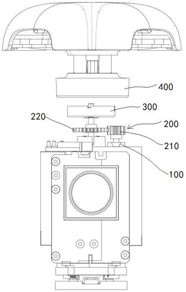
[0054] refer to Figure 5 As shown, the electric shaver includes a motor bracket 500, the motor 100 is fixed on the lower housing B through the motor bracket 500, the motor bracket 500 covers the upper end of the motor, and the drive shaft 110 of the motor 100 runs through The motor bracket 500 is then connected to the gear assembly 200 .

[0055] Because the motor will vibrate to a certain extent during the rotation process, in order to reduce the vibration, a fixed motor bracket is used, and the motor bracket only fixes the upper end of the motor. Since the output force of the drive shaft is output from the drive shaft, the upper end of the motor is firmly If it is firmly fixed, the expected effect can be achieved, that is, the technical effect of reducing vibration to the greatest extent is achieved by using few materials.

[0056] Furth...

Embodiment 3

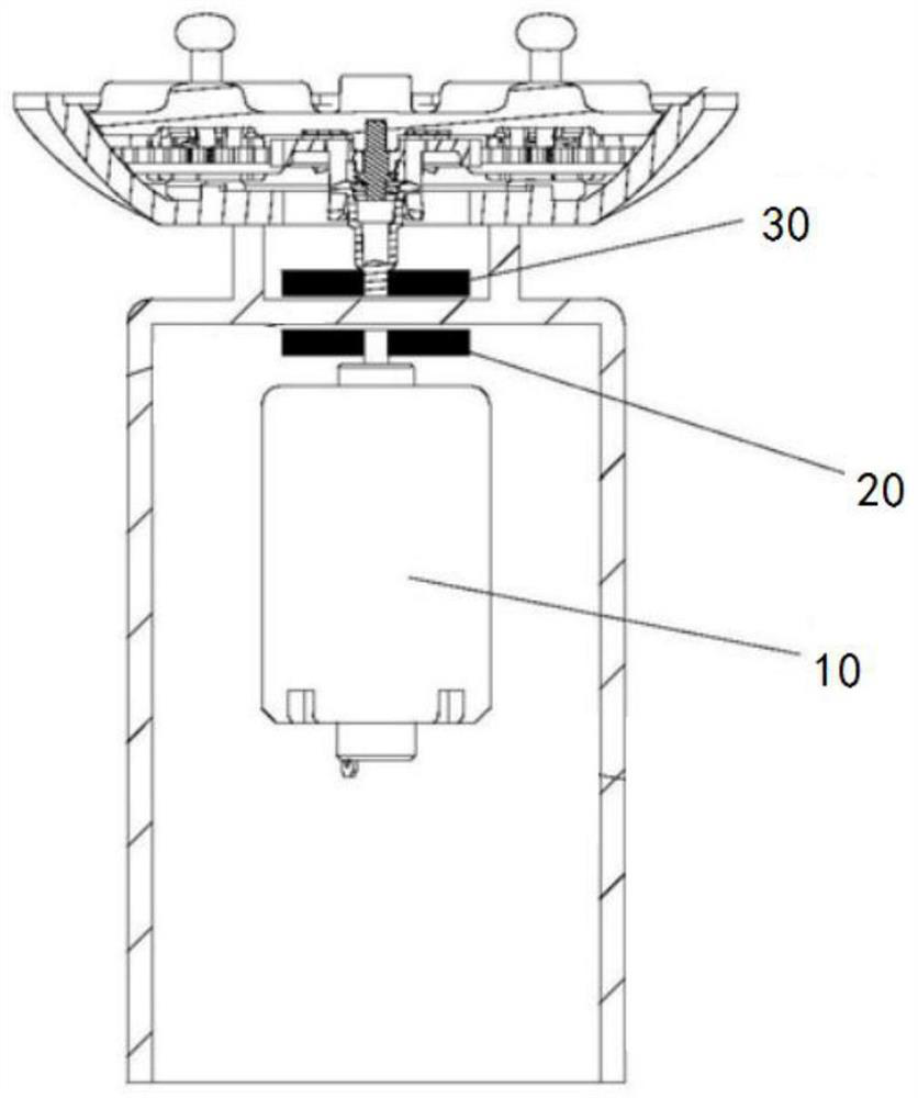
[0066] In addition to the electric shaver as described in Embodiment 1-Example 2, it also includes an auxiliary magnetic assembly, wherein the auxiliary magnetic assembly is only used to magnetically fix the upper shell and the lower shell, and the working state does not rotate .

[0067] refer to Figure 7 As shown, in this solution, the auxiliary magnetic attraction assembly includes a lower auxiliary magnet 310 and an upper auxiliary magnet 410 , and the magnetism corresponding to the longitudinal direction of the lower auxiliary magnet and the upper auxiliary magnet is in a state of opposite sex attraction.

[0068]Compared with the active magnet and the driven magnet, the auxiliary magnetic assembly can rotate, and it is in a static state, that is, the corresponding lower auxiliary magnet and upper auxiliary magnet are firmly fixed on the installation position, and the auxiliary magnetic assembly only serves as a pure suction. The combined action to connect the lower she...


PUM


Abstract

The invention provides an electric shaver which comprises a main body assembly and a head cover assembly, wherein the main body assembly comprises a lower shell and a driving unit arranged in the lower shell, the head cover assembly comprises a movable knife unit and an upper shell used for supporting the movable knife unit, a driving magnetic assembly is embedded in the lower shell, and a drivenmagnetic assembly is embedded in the upper shell; when the electric shaver is in a static and longitudinally-placed state, the magnetism, corresponding to the longitudinal direction, of the driving magnetic assembly and the magnetism, corresponding to the longitudinal direction, of the driven magnetic assembly are in an unlike attraction state, the driving unit comprises a motor, and the movable shaver unit is driven to rotate under the action of the motor, the driving magnetic assembly and the driven magnetic assembly; and the central axis of the driving magnetic assembly and the central axisof the driven magnetic assembly coincide with the central axis of the electric shaver, and the central axis of the motor deviates from the central axis of the electric shaver by 4-8 cm. The motor deviates from the central axis of the electric shaver, and the influence of vibration generated by rotation of the motor on the magnet is minimum.

Description

technical field [0001] The invention relates to the field of household appliances, in particular to an electric shaver. Background technique [0002] An existing electric shaver includes a hand-held part and a cutter head part, wherein the drive of the hand-held part and the cutter head part is transmitted by a pivot extending from the hand-held part through the pivot coupling the cutter head part. The disadvantages of this method are obvious: increased noise, increased load, and the seal ring is required to seal the pivot shaft. Long-term use will cause leakage after the seal ring is aged and worn. [0003] There is also an electric shaver, such as the structure disclosed in reference document 1 (201820512427.3), which adopts a magnetic attraction method to connect the hand-held part and the cutter head part, such as figure 1 As shown, it includes the motor 10 located on the central axis, and the upper magnet 30 located on the upper part, and the lower magnet 20 located on...

Claims


Application Information

Patent Timeline
Patent Type & Authority Applications(China)
IPC IPC(8): B26B19/38B26B19/14B26B19/28
CPCB26B19/3806B26B19/14B26B19/28
Inventor 祝永锋叶志文肖林
Owner HUANXING TECH HANGZHOU CO LTD
Why Eureka
Try Eureka