
Assembling and welding mould for thin-wall rectangular beam and using method thereof

A technology of rectangular beams and moulds, applied in welding equipment, auxiliary welding equipment, welding/cutting auxiliary equipment, etc., to achieve fast welding, save welding positioning, and high welding efficiency

Inactive Publication Date: 2020-11-17
XI'AN UNIVERSITY OF ARCHITECTURE AND TECHNOLOGY
View PDF9 Cites 0 Cited by
  • Summary
  • Abstract
  • Description
  • Claims
  • Application Information

AI Technical Summary

Problems solved by technology

[0004] Aiming at the technical problems existing in the prior art, the present invention provides an assembly and welding mold for thin-walled rectangular beams and its use method to solve the existing process of assembling and welding thin-walled rectangular beams, the positioning process is complicated, and the flipping It is more difficult, and it is easy to cause cracking and deformation of the workpiece, and the yield of assembly and welding is low

Method used


Image

  • Assembling and welding mould for thin-wall rectangular beam and using method thereof
  • Assembling and welding mould for thin-wall rectangular beam and using method thereof
  • Assembling and welding mould for thin-wall rectangular beam and using method thereof

Examples


Embodiment 1

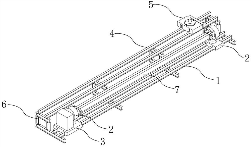
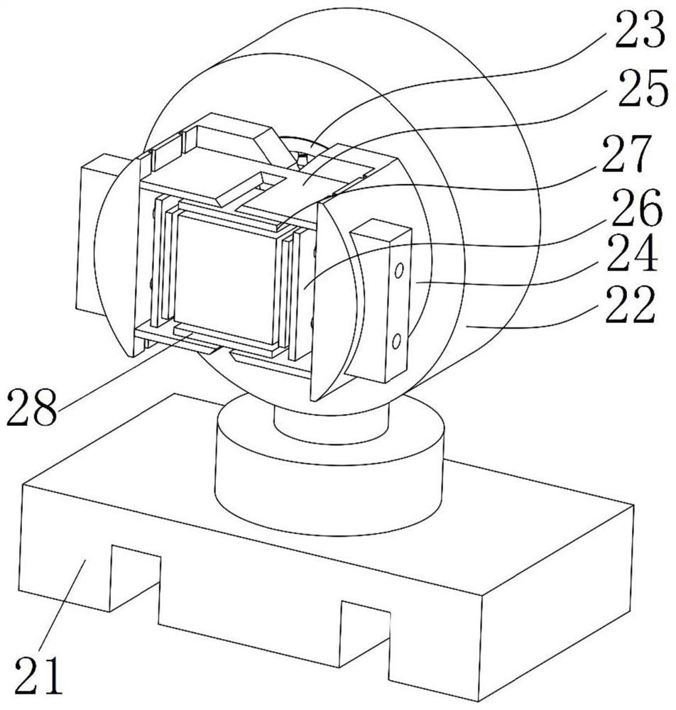
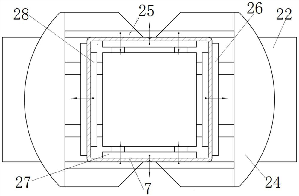
[0052] Embodiment 1 provides a thin-walled rectangular beam assembly welding mold, including automatic welding machine, welding machine guide rail, frame, chuck, chuck guide rail and power mechanism;

[0053] Install the welding machine guide rail and chuck guide rail horizontally on the frame, the automatic welding machine is installed on the welding machine guide rail, and the automatic welding machine can move horizontally along the welding machine guide rail; the chuck is installed on the chuck guide rail, and the workpiece to be welded It is clamped by the chuck; the power mechanism is set on one of the chucks, and the drive motor in the power mechanism is connected to the rotating bearing in the chuck through the transmission shaft. When the drive motor outputs power through the transmission shaft to rotate the bearing, the drive splint The rotation of the bracket, and then the workpiece to be welded rotates around its own axis, so as to realize the smooth turning of the ...

Embodiment 2

[0066] The difference from the above-mentioned embodiment 1 is that the power mechanism can also be removed, and the motor is installed on the chuck bracket to drive the workpiece to rotate around its own axis; the motor adopts a stepping motor or a synchronous motor.

Embodiment 3

[0068] The difference from the above-mentioned embodiment 1 is that when the workpiece to be welded has other shapes, the chuck can be replaced to change the shape of the inner splint and the outer splint to adapt to the shape of the workpiece to be welded at this time.

[0069] The assembled welding mold for thin-walled rectangular beams and the method of use thereof according to the present invention use the chuck to perform lateral positioning of the workpiece to be welded, so as to achieve rapid positioning; the inner splint and outer splint in the chuck realize the The workpiece to be welded is clamped, so that the welding parts of the workpiece to be welded can be quickly aligned, which is convenient for fast welding; by setting a power mechanism on the chuck bracket, the power mechanism drives the splint bracket to rotate, thereby realizing the smooth turning of the entire workpiece, avoiding the traditional When the welding method manually moves the workpiece, it will c...


PUM


Abstract

The invention discloses an assembling and welding mould for a thin-wall rectangular beam and a using method thereof. The assembling and welding mould comprises chuck guide rails, the chuck guide railsare horizontally arranged in parallel with a welding machine guide rail, and two chucks are symmetrically arranged on the chuck guide rails; a to-be-welded workpiece is horizontally arranged betweenthe two chucks, and the chucks are used for clamping the end of the to-be-welded workpiece and can drive the to-be-welded workpiece to rotate around the axes of the chucks; and a welding machine is arranged on the welding machine guide rail in a sliding manner and used for welding the to-be-welded workpiece. According to the assembling and welding mould, the two chucks are used for clamping the to-be-welded workpiece, so that transverse positioning of the to-be-welded workpiece is achieved, and the positioning process is simple, rapid and accurate; the chucks drive the to-be-welded workpiece to rotate, so that the whole workpiece is stably overturned, and cracking, deformation or positioning failures of the workpiece in the overturning process is avoided; and the welding machine is arranged on the welding machine guide rail in the sliding manner, so that rapid welding of the to-be-welded workpiece is achieved through movement of the welding machine, the welding efficiency is high, andthe assembling and welding yield is high.

Description

technical field [0001] The invention belongs to the technical field of assembling and welding of thin-walled rectangular beams, and in particular relates to an assembling and welding mold for thin-walled rectangular beams and a method for using the same. Background technique [0002] With the development of industrialization, the development of technical fields such as construction industry and engineering vehicles is advancing by leaps and bounds. In these application fields, a large number of thin-walled rectangular beams of different shapes are involved and used; in the assembly and welding of thin-walled rectangular beams, positioning, Flipping is a relatively important operation; in the prior art, the welding of thin-walled rectangular beams is more complicated, the beam wall is thinner, the length is longer, and it is assembled structure welding, which usually requires manual positioning and flipping, and the efficiency is low. [0003] At present, there are mainly the...

Claims


Application Information

Patent Timeline
Patent Type & Authority Applications(China)
IPC IPC(8): B23K37/04B23K37/047B23K37/02
CPCB23K37/0435B23K37/047B23K37/0211
Inventor 王发展李汶轩李哲
Owner XI'AN UNIVERSITY OF ARCHITECTURE AND TECHNOLOGY
Learn More