
Moderately-thick aluminium alloy plate laser welding device and method

A laser welding, aluminum alloy technology, applied in laser welding equipment, welding equipment, metal processing equipment and other directions, can solve the problem of reducing the effect of removing pores and so on

Inactive Publication Date: 2020-11-17
HUAZHONG UNIV OF SCI & TECH
View PDF5 Cites 3 Cited by
  • Summary
  • Abstract
  • Description
  • Claims
  • Application Information

AI Technical Summary

Problems solved by technology

If low-frequency oscillation is used, although the depth of penetration is improved to a certain extent, the effect of removing pores is correspondingly reduced

Method used


Image

  • Moderately-thick aluminium alloy plate laser welding device and method
  • Moderately-thick aluminium alloy plate laser welding device and method
  • Moderately-thick aluminium alloy plate laser welding device and method

Examples


Embodiment 1

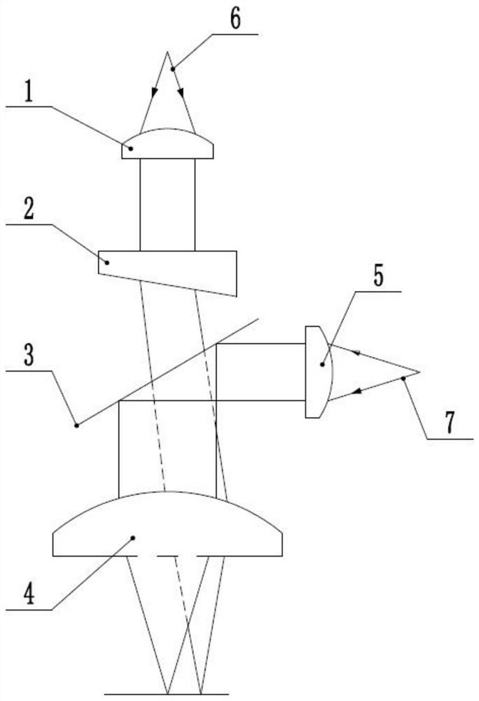
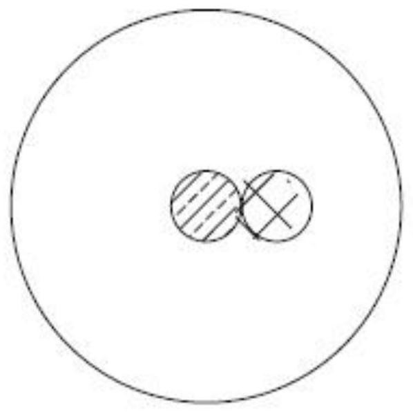
[0038] This embodiment provides a laser welding device for aluminum alloy medium and thick plates, such as Figure 1-Figure 8 As shown, including a first laser, a second laser, a first collimating mirror 1, a refracting mirror 2, a rotating platform, a reflecting mirror 3, a focusing mirror 4 and a second collimating mirror 5, both the first laser and the second laser can Move, the first laser can emit the first beam 6, the second laser can emit the second beam 7, the wavelength of the first beam 6 and the second beam 7 are different, the first collimating mirror 1 is facing the outgoing direction of the first beam 6 Set, the diameter of the first collimating mirror 1 is larger than the cross-sectional diameter of the first beam 6 cut off by the first collimating mirror 1, the first collimating mirror 1 can adjust the first beam 6 to a parallel beam, and the refracting mirror 2 is facing The first collimating mirror 1 is set, there is a gap between the refracting mirror 2 and ...

Embodiment 2

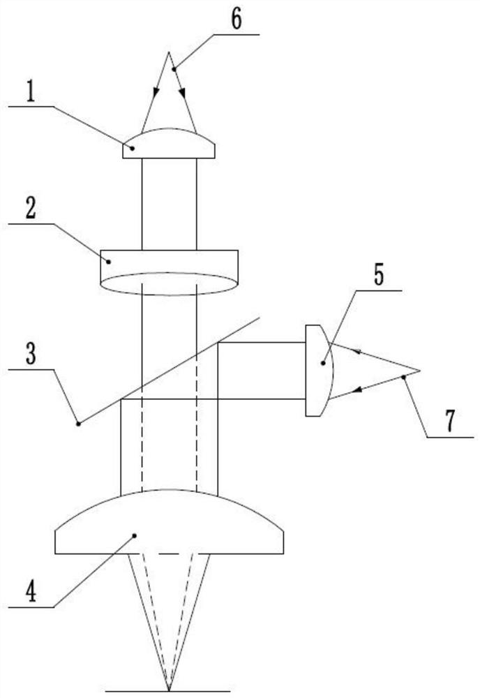
[0049] This embodiment is a further improvement made on the basis of Embodiment 1, as Figure 9 As shown, the present embodiment removes the refracting mirror on the basis of Embodiment 1; the center point of the reflecting mirror 3 is located on the axis of the focusing mirror 4, and the center line of the first collimating mirror 1 and the axis of the focusing mirror 4 have an eccentricity d, the eccentricity d ranges from 0 to 5 mm; the first collimating mirror 1 is connected with a rotating platform, and the rotating platform can drive the first collimating mirror 1 to rotate around the axis of the focusing mirror 4 with an eccentricity d.

[0050] Therefore, in the laser welding method for aluminum alloy medium and thick plates provided in this embodiment, the second beam 7 moves along the weld seam direction of the workpiece to be welded, and the focused second beam 7 moves along the weld seam direction of the workpiece to be welded At the same time, the rotating platfor...


PUM

PropertyMeasurementUnit
Wavelengthaaaaaaaaaa
Spot diameteraaaaaaaaaa

Abstract

The invention discloses a moderately-thick aluminium alloy plate laser welding device and method, and relates to the technical field of laser welding. The device comprises a first laser, a second laser, a first collimating mirror, a refractor, a rotating platform, a reflection mirror, a focusing mirror and a second collimating mirror, wherein the first laser can emit a first beam, the second lasercan emit a second beam, the top surface of the refractor is a flat surface, and faces the first collimating mirror, the bottom surface of the refractor is an oblique surface, and the refractor is connected with the rotating platform; and the reflection mirror can reflect the second beam, the first beam can penetrate through the reflection mirror, and the focusing mirror can focus the first beam and the second beam. The moderately-thick aluminium alloy plate laser welding method is provided. The moderately-thick aluminium alloy plate laser welding method comprises the steps of making the second beam move in a direction of a welding seam of a to-be-welded workpiece, and meanwhile, making the first beam rotate around the focused second beam. By means of the second beam, welding penetration can be guaranteed, and the first beam rotates around the second beam to stir a weld pool so that pores can be eliminated.

Description

technical field [0001] The invention relates to the technical field of laser welding, in particular to a laser welding device and method for aluminum alloy medium and thick plates. Background technique [0002] Aluminum alloy plate welding is a key technology in the manufacturing process of high-performance equipment for major national strategic projects such as aerospace, energy chemical industry, and rail transit. Although the traditional arc welding method has the advantages of simple equipment, convenient operation, and low cost, it has been gradually replaced by more advanced laser welding due to its problems such as extremely low efficiency, poor weld quality, and harsh operating environment. Laser welding has become a widespread trend for components that require high welding performance. [0003] However, during the laser welding process, part of the molten pool is gasified and plasmaized, forming a unique keyhole (keyhole) structure, and the inner surface of the key...

Claims


Application Information

Patent Timeline
IPC IPC(8): B23K26/21B23K26/046B23K26/064B23K26/70
CPCB23K26/046B23K26/0643B23K26/21B23K26/702
Inventor 马修泉许天宇米高阳周邵巍邵新宇
Owner HUAZHONG UNIV OF SCI & TECH
Learn More