Distributed blank-holding force generating device and control method for electro-permanent-magnet composite box-type stamping process

A generation device, electric permanent magnet technology, applied in the direction of manufacturing tools, metal processing, metal processing equipment, etc., can solve the problems of limited blank-holding force, increased equipment energy consumption, and failure to consider blank-holding force, etc., to achieve improved The ability to generate electromagnetic force, improve molding quality, and reduce energy consumption

Active Publication Date: 2022-03-15
HEFEI UNIV OF TECH
View PDF0 Cites 0 Cited by
  • Summary
  • Abstract
  • Description
  • Claims
  • Application Information

AI Technical Summary

Problems solved by technology

The current BHF control methods mainly include the optimization of the BHF curve in a single area over time, and the BHF control method in which the BHF varies with the position of the circumferential block, but it does not take into account the change of the BHF during the stamping process. , and did not take into account the impact of changes in blank holder force on equipment energy consumption, resulting in an increase in equipment energy consumption
[0004] The current single electromagnetic distributed blank-holding method provides a limited blank-holding force, and cannot even meet the blank-holding force requirements of some special material boxes when stamping.

Method used


Image

  • Distributed blank-holding force generating device and control method for electro-permanent-magnet composite box-type stamping process
  • Distributed blank-holding force generating device and control method for electro-permanent-magnet composite box-type stamping process
  • Distributed blank-holding force generating device and control method for electro-permanent-magnet composite box-type stamping process

Examples


Embodiment Construction

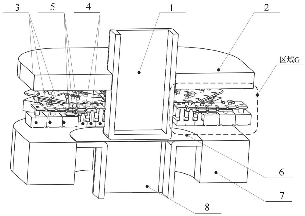
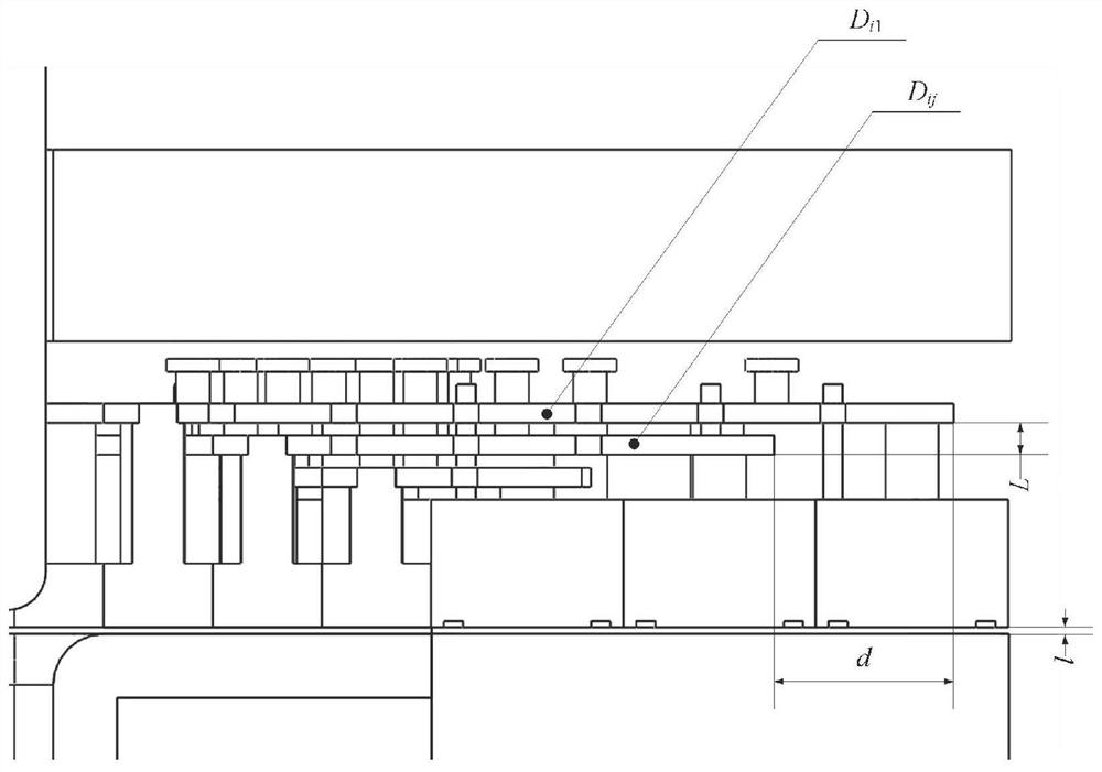
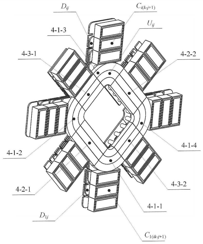
[0047] In this example, if figure 1 As shown, a distributed blank-holding force generating device and control method of a box-type stamping process of electro-permanent magnet composite is to place an electronically controlled permanent magnetic chuck 7 horizontally at the bottom, and the electronically controlled permanent magnetic chuck 7 is box-shaped. A box-shaped die 8 is provided; the upper surface of the die 8 is flush with the upper surface of the electric permanent magnet chuck 7, and the upper surface of the electric permanent magnet chuck 7 is a magnetic force generating surface, and on the upper surface of the die 8 A sheet material 6 is placed on it; just above the sheet material 6 is a blank holder 4; as Figure 4 As shown, the blank holder 4 is divided into 8 areas in the counterclockwise direction in the circumferential direction, including 4 rounded areas, 2 long-side areas and 2 short-side areas; wherein, the i-th area is along the radial direction and from t...


PUM


Abstract

The invention discloses a distributed blank-holding force generating device and a control method for a box-type stamping process combined with electric permanent magnets. The device is composed of a blank-holding ring guiding device, an electromagnetic force generating device, a blank-holding ring, and an electronically controlled permanent magnet sucker ;According to the deformation characteristics of the box-shaped parts, distributed blank-holding devices with different maximum blank-holding forces are arranged on the long side, short side and rounded corner area, which matches the blank-holding force and blank-holding force demand generated in each area, and reduces the The energy consumption of the forming process; the introduction of electronically controlled permanent magnet chucks, the deployment of the electromagnetic force of the distributed edge-holding device, while improving the electromagnetic force generation capacity of each edge-holding block, reduce the energy consumption of the distributed edge-holding block; The edge ring is equipped with a displacement sensor. By monitoring the change of the thickness of the sheet material at each distributed blank-holding position, the blank-holding force of the distributed blank-holding block is adjusted in real time, so as to realize the accurate and controllable loading path of the distributed blank-holding force during the stamping process, thereby improving the stamping process. Forming quality of the part.

Description

technical field [0001] The invention relates to a blank-holding system and a control method of a stamping process, a distributed blank-holding force generating device and a control method of an electro-permanent-magnet composite box-shaped stamping process. Background technique [0002] Stamping processing is one of the main methods of metal plastic processing, which belongs to material forming engineering technology, including basic processes such as blanking, deep drawing, bending, punching, flanging, and shaping. It has high production efficiency, less waste, and surface The advantages of low roughness and the ability to process parts with complex shapes. [0003] The blank holder force is one of the important parameters in stamping forming. Proper control of the blank holder force is conducive to improving the forming quality of the stamping parts, improving the stress and strain state of the sheet during the stamping process, and then affecting its forming limit, cracki...

Claims


Application Information

Patent Timeline
Patent Type & Authority Patents(China)
IPC IPC(8): B21D26/14B21D51/52B21C51/00
CPCB21D26/14B21D51/52B21C51/00
Inventor 李磊黄海鸿吕清宇甘雷李新宇董光旭刘志峰
Owner HEFEI UNIV OF TECH
Why Eureka
Try Eureka