Eureka AIR delivers breakthrough ideas for toughest innovation challenges, trusted by R&D personnel around the world.

Automatic turnover type plate surface spraying device

An automatic flipping and surface spraying technology, which is applied in spraying devices, liquid spraying devices, etc., can solve the problems that the plate cannot be turned over automatically and the degree of spraying automation is low, so as to achieve the effect of improving the automation function and improving the uniformity of dispersion

Active Publication Date: 2020-11-17
濉溪县安乐殡仪服务有限公司
View PDF8 Cites 6 Cited by
  • Summary
  • Abstract
  • Description
  • Claims
  • Application Information

AI Technical Summary

Problems solved by technology

The board surface spraying device uses clamps to squeeze the compression spring and cooperate with the rollers to effectively fix the board on the conveyor belt, avoiding the board not moving with the conveyor belt during spraying, and effectively using the rollers to The friction of the plate on the pallet is reduced, resulting in uneven coating of the plate, but there are still defects. The plate cannot be turned over automatically during spraying, resulting in a low degree of automation in spraying

Method used


Image

  • Automatic turnover type plate surface spraying device
  • Automatic turnover type plate surface spraying device
  • Automatic turnover type plate surface spraying device

Examples


Embodiment 1

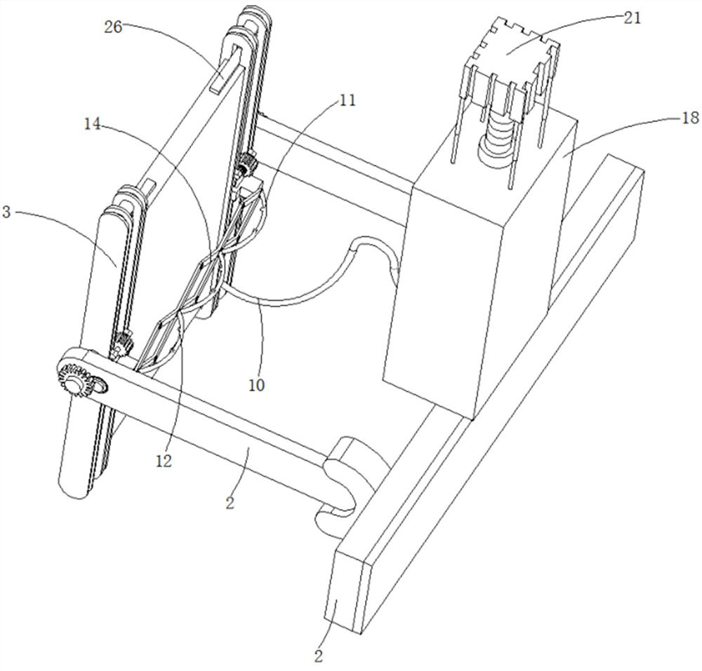
[0036] refer to Figure 1-8 , an automatic flip-type plate surface spraying device, including a mounting base 1, a symmetrically distributed support plate 2 is connected to the mounting base 1, a spraying assembly is arranged on the outside of the mounting base 1, and a liquid outlet pipe 10 is connected to the spraying end of the spraying assembly. , the opposite side of the support plate 2 is connected with the installation plate 3 through the rotation of the shaft, and one end of the shaft passing through the support plate 2 is connected with an intermittent rotation mechanism fixed on the support plate 2, and the installation plate 3 is provided with a The two tooth plates 4 are evenly and symmetrically distributed in the length direction, and the two tooth plates 4 have an arc transition. The mounting plate 3 is also provided with a chute 5 parallel to the tooth plate 4, and the chute 5 is slidably connected with an active slide. The block 6 and the driven slider 7, and t...

Embodiment 2

[0044] refer to Figure 1-8 , an automatic flip-type plate surface spraying device, including a mounting base 1, a symmetrically distributed support plate 2 is connected to the mounting base 1, a spraying assembly is arranged on the outside of the mounting base 1, and a liquid outlet pipe 10 is connected to the spraying end of the spraying assembly. , the opposite side of the support plate 2 is connected with the installation plate 3 through the rotation of the shaft, and one end of the shaft passing through the support plate 2 is connected with an intermittent rotation mechanism fixed on the support plate 2, and the installation plate 3 is provided with a The two tooth plates 4 are evenly and symmetrically distributed in the length direction, and the two tooth plates 4 have an arc transition. The mounting plate 3 is also provided with a chute 5 parallel to the tooth plate 4, and the chute 5 is slidably connected with an active slide. The block 6 and the driven slider 7, and t...


PUM


Abstract

The invention discloses an automatic turnover type plate surface spraying device and a using method thereof, and belongs to the technical field of plate surface spraying devices. The automatic turnover type plate surface spraying device comprises a mounting base, symmetrically-distributed supporting plates are connected to the mounting base, a spraying assembly is arranged at the outer side of themounting base, the spraying end of the spraying assembly is connected with a liquid outlet pipe, and the opposite sides of the supporting plates are rotationally connected with mounting plates through rotating shafts; the ends, penetrating through the supporting plates, of the rotating shafts are connected with intermittent rotating mechanisms fixedly connected to the supporting plates, two toothed plates which are evenly and symmetrically distributed in the length direction of the mounting plate are arranged on each mounting plate, arc transition is formed between the two toothed plates on each mounting plate, sliding grooves parallel to the toothed plates are further formed in the mounting plates, and driving sliding blocks and driven sliding blocks are slidably connected into the sliding grooves; and connecting pieces are connected between the driving sliding blocks and the driven sliding blocks, and the driving sliding blocks are connected with driving gears meshed with the toothed plates. According to the automatic turnover type plate surface spraying device, the automatic turnover function of a plate during spraying is realized.

Description

technical field [0001] The invention relates to the technical field of plate surface spraying devices, in particular to an automatic flip-type plate surface spraying device. Background technique [0002] Plate products have a flat shape, a large aspect ratio, and a large surface area per unit volume. This shape has a large surface area, so it has a strong ability to contain and cover. It is widely used in chemical industry, containers, construction, metal products, and metal structures. [0003] In the prior art, the invention patent with the patent application number 201710574681.6 discloses "a device for spraying the surface of a plate, including a box body, a third connecting pipe is installed on the top of the box body, and a third connecting pipe is installed on the right side of the third connecting pipe. There is a first connecting pipe, a paint box is installed on the right side of the first connecting pipe, a conveyor belt is provided at the bottom of the box body, ...

Claims


Application Information

Patent Timeline
IPC IPC(8): B05B9/047B05B13/02B05B15/68
CPCB05B9/047B05B13/0228B05B13/0278B05B13/0285B05B15/68
Inventor 黄菊花
Owner 濉溪县安乐殡仪服务有限公司
Why Eureka
Eureka Blog
Learn More