
Parturient obstetric apparatus for gynaecology and obstetrics department

A technology of obstetrics and gynecology, midwifery device, applied in obstetrics and gynecology equipment, medical science, surgery and other directions, can solve the problem of inflation and inflation speed is not easy to be too fast, to avoid increased pain, good fit, improve The effect of connection strength

Pending Publication Date: 2020-11-17
民勤县人民医院
View PDF0 Cites 4 Cited by
  • Summary
  • Abstract
  • Description
  • Claims
  • Application Information

AI Technical Summary

Problems solved by technology

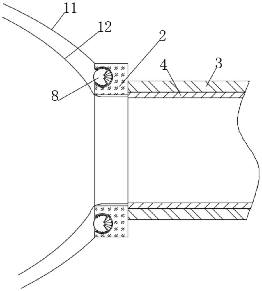
[0005] Aiming at the problems existing in the prior art, the purpose of the present invention is to provide an obstetrics and gynecology delivery aid, through the structure of the double-layered airbags of the outer sealed airbag and the inner semi-permeable airbag, it can effectively ensure that the airbag can effectively expand the birth canal. , the speed of inflating and expanding is not easy to be too fast, which can effectively avoid the situation that the birth canal is stretched too fast and cause discomfort to the parturient. As a result, the gas gradually enters between the outer sealing airbag and the inner semi-permeable airbag. At this time, under the action of the gas, the two sides of the expansion pressure ring extend and squeeze toward the inner wall of the annular ball groove. As the gas gradually increases, the gas squeezes As the pressure increases, the connection strength between the outer sealing airbag and the air pressure ring and the effect of sealing become stronger and stronger, effectively avoiding gas leakage or airbag falling off, and effectively improving the safety during midwifery

Method used


Image

  • Parturient obstetric apparatus for gynaecology and obstetrics department
  • Parturient obstetric apparatus for gynaecology and obstetrics department
  • Parturient obstetric apparatus for gynaecology and obstetrics department

Examples


Embodiment 1

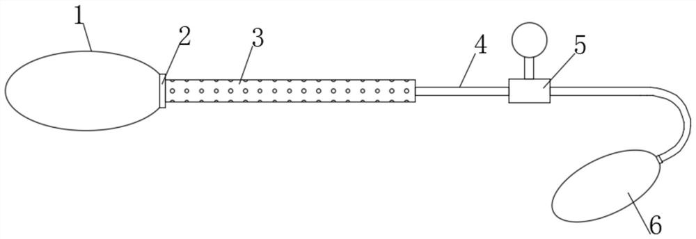
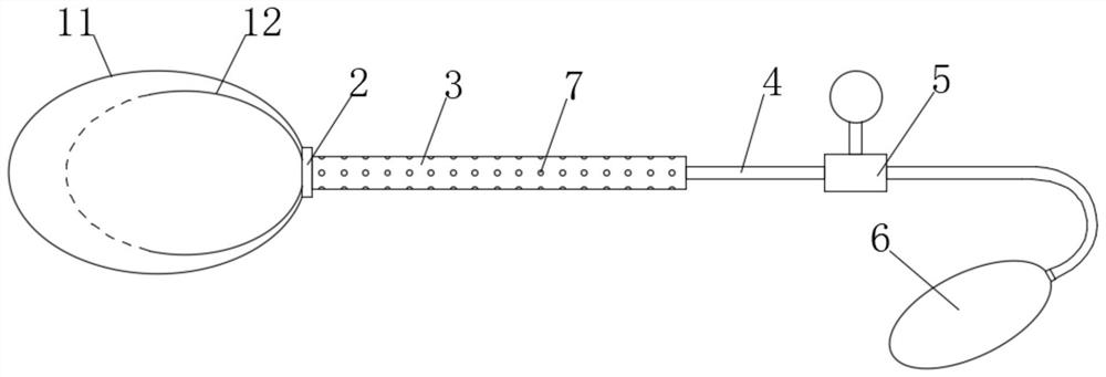
[0040] see figure 1 , an obstetrics and gynecology delivery aid, comprising a slow double-layer airbag 1, the end of the slow double-layer airbag 1 is fixedly connected with an air pressure ring 2, and the end of the air pressure ring 2 away from the slow-speed double-layer airbag 1 is fixedly connected with silica gel Tube 4, the outer end of the silicone tube 4 is covered with a handle 3, the part of the silicone tube 4 outside the handle 3 is connected with a tee tube 5, a pressure gauge is installed on the tee tube 5, and the end of the silicone tube 4 away from the handle 3 is fixedly connected There is a manually pressurized airbag 6 with a valve, and the manually pressurized airbag 6, the three-way pipe 5, the silicone tube 4, the air pressure ring 2 and the retarding double-layer airbag 1 communicate in sequence.

[0041] see Figure 3-4 The slow speed double-layer airbag 1 includes an inner semi-permeable airbag 12 and an outer sealed airbag 11 sleeved outside the in...


PUM


Abstract

The invention discloses a parturient obstetric device for gynaecology and obstetrics department, belongs to the field of obstetric devices,. According to the parturient obstetric device for gynaecology and obstetrics department, the inflation and expansion speed is not too high when an air bag is used for expanding a birth canal through a double-layer air bag structure of an outer sealing air bagand an inner semi-permeable air bag. The condition that the birth canal expansion speed is too high, and a lying-in women feels uncomfortable, can be avoided effectively. In the later stage of birth canal expansion, after the outer sealing air bag and the inner semi-permeable air bag are separated, under the action of an expansion pressing ring, air gradually enters the space between the outer sealing air bag and the inner semi-permeable air bag, and at the moment, under the action of the air, two sides of the expansion pressing ring extend and squeeze towards the inner wall of an annular ballgroove, so that the air squeezing force becomes larger and larger along with gradual increase of air, the effect that the connecting strength and the sealing performance of the outer sealing air bagand an air pressure ring become higher and higher can be achieved, the situation of air leakage or falling off of the air bags is effectively avoided, and the safety during the whole obstetric processis effectively improved.

Description

technical field [0001] The invention relates to the field of obstetrics and gynecology, and more specifically, relates to an obstetrics and gynecology delivery aid. Background technique [0002] Midwifery device, a kind of midwifery device for obstetrical midwifery, which is easy to operate, can reduce head injury and speed up delivery. The midwifery device is composed of a suction device and a dilator. The suction device is composed of a silicone rubber suction cup and a negative pressure device. The negative pressure device is equipped with a negative pressure cylinder, and a piston with a connecting rod is installed in the negative pressure cylinder. The negative pressure cylinder in the opposite direction of the suction cup is provided with an extension part, and the expander is provided with blades and adjustment handles, the adjustment handle and the extension part move up and down through corresponding tracks, and the blades and the negative pressure cylinder are mova...

Claims


Application Information

Patent Timeline
IPC IPC(8): A61B17/02A61B17/42
CPCA61B17/02A61B17/42
Inventor 李琼石一超李玉兰张艳红刘发生
Owner 民勤县人民医院
Learn More